


32
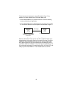
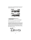
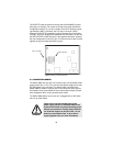
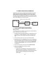
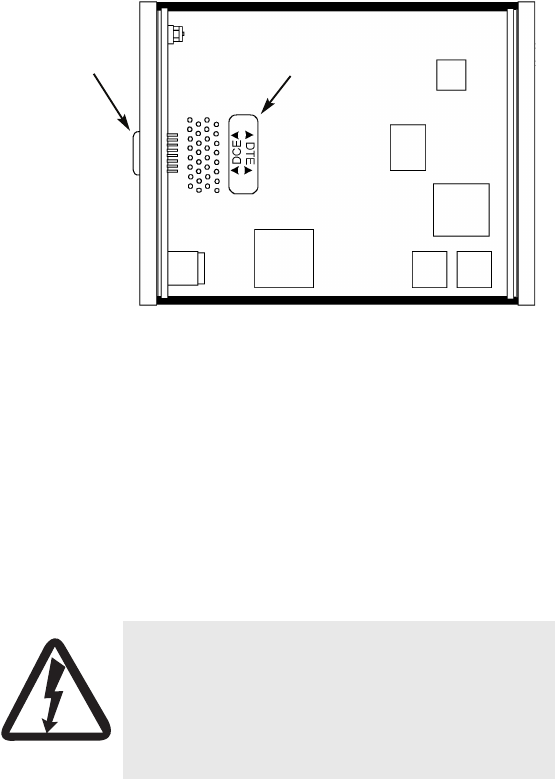
The DCE/DTE strap is located on the top side of the 3088/D pc board
(See figure 10, below). The arrows on the top of the strap indicate the
configuration of the X.21 port (for example, if the DCE arrows are point-
ing toward the DB-15 connector, the X.21 port is wired as a DCE).
Change the DCE/DTE orientation by pulling the strap out of its socket,
rotating it 180º, then plugging the strap back into the socket. You will see
that the DCE/DTE arrows now point in the opposite directions, showing
the new configuration of the X.21 port. To close the case, fit the 2 halves
together snugly and snap them back in place.
Figure 10. Setting the DCE/DTE Strap
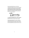
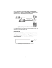
5.4 CONNECTING POWER
The Model 3088 uses a 5 VDC, 2A universal input 100–240 VAC, power
supply (center pin is +5V). The universal input power supply has a male
IEC-320 power entry connector. This power supply connects to the
Model 3088 by means of a barrel jack on the rear panel. Many interna-
tional power cords are available for the universal power supply (Please
refer to Appendix B for country-specific power cords.
The Model 3088 powers up as soon as it is plugged into an AC outlet--
there is no power switch.
WARNING
There are no user-serviceable parts in the
power supply section of the Model 3088. Fuse
replacement should only be performed by quali-
fied service personnel. Contact Patton Electron-
ics Technical support at (301)975-1007, via our
web site at www.patton.com, or by e-mail at
support@patton.com, for more information.
DCE/DTE Strap
DB-15 Connector