


35
.
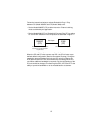
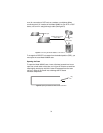
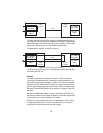
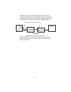
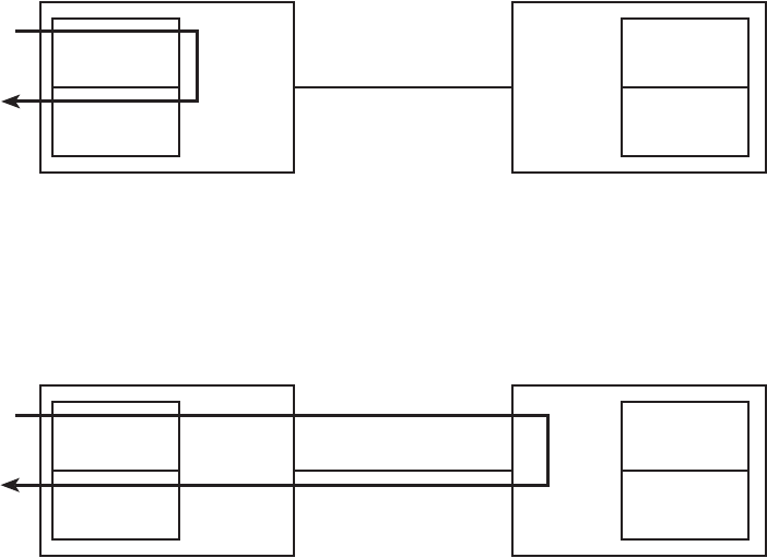
Figure 13. Local Analog Loopback diagram
The data received from the serial interface is looped back before going
out on the DSL line. Note that this loopback occurs after the pattern gen-
erator/BER meter. This means that running a 511 pattern is conjunction
with an LAL should result in no error detected by the meter.
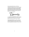
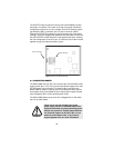
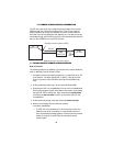
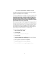
The data path for the RDL is shown in figure 14.
Figure 14. Remote Digital Loopback diagram
The RDL causes the remote unit to loop the data received from the DSL
line back to the DSL line.
Patterns
The 3088 can generate and detect 511 and 511 with Error patterns.
These can be initiated either by the optional front panel switches or by
the console command dsl set pattern <off|511|511e>. When the pattern
is started, the DSL framer uses its internal 511 pattern generator for its
DSL TX data instead of the data received from the serial interface. Also,
the framer’s internal BER Meter tries to detect a 511 pattern in the DSL
RX Data.
Because the BER Meter always runs when the pattern generator runs,
the meter will detect errors if either the pattern is not either looped back
or the remote unit is not transmitting a 511 pattern.
One point to note is that the way errors are generated in the 511E pat-
tern generates CRC errors. This can cause the DSL error monitor to
restart the link if the thresholds are set low enough.
DSL
Framer
511 Pattern
Generator
511 BER
Meter
DSL
Framer
511 Pattern
Generator
511 BER
Meter
Line
DSL
Framer
511 Pattern
Generator
511 BER
Meter
DSL
Framer
511 Pattern
Generator
511 BER
Meter
Line