


SP / TC / GT
PAGE 9
CENTURY SERIES
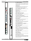
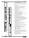
MONO Bus Assign Switch
Assigns the post-fader input signal directly to the Mono Clean
bus.
Bus Assign Switches (L/R, 1-8)
Assigns the post Pan Signals to the mix bus in odd/even pairs.
Pan controls assignment between these two mix buses with
extreme left pan assigning signal exclusively to the odd mix
bus and extreme right pan assigning signal exclusively to the
even mix bus. When the pan is in its center position, signal is
fed equally to the odd (left) and even (right) mix bus. When
used in stereo applications, the channel signal may be located
anywhere within the stereo image as controlled by the Pan con-
trol.
PFL Switch
Samples the channel’s signal pre-fader and allows for monitor-
ing within the master section of the console. This signal is not
affected by the Mute Switch. When depressed, the signal level
can be seen on the Left/Right meters, and heard via the mixer’s
headphone or local monitor output. When this PFL Switch is
depressed, the channel PEAK LED indicator illuminates at a
lower intensity. When used as a status indicator of switch posi-
tion, the Peak LED indicating circuit remains fully operational
by illuminating at a much higher intensity than its use as a PFL
status indicator.
PEAK LED Indicator
Illuminates RED when any of the points monitored come with-
in 3db of the clipping point. Signal is sampled after the input
preamplifier stage, after the EQ section, and after the fader.
This LED also serves as a PFL ON indicator, but at a much
lower intensity than when it is used to indicate clipping.
SIGNAL PRESENT LED
Constantly displays level activity of the input channel by vary-
ing in intensity.
100mm Fader
Used for control of all outputs of the channel except those Aux
output sections selected by switch to a pre fader position. (The
Insert Output level is not affected by the fader position.)
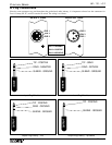
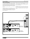
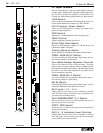
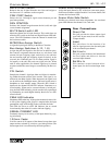
Rear Connections
Direct Out
This jack provides the direct output signal
(post fader & post mute) from the associat-
ed input channel.
Insert
This jack allows for the insertion of an
effect or signal processor into the audio path
of the associated input channel.
Bal Line In
This jack accepts balanced and unbalanced
line level inputs and delivers it into the
associated input channel.
Bal Mic In
This connector accepts balanced micro-
phone inputs for the associated input chan-
nel.
BAL
LINE IN
DIR OUT
INSERT
BALMIC
IN