


SP / TC / GT
APPENDIX A
CENTURY SERIES
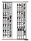
General Specifications -
SP Console
The following are the technical specifications for the Century
SP console.
Architect’s & Engineer’s
Specifications - SP Console
The following text should be used when specifying a Century
SP in a bid or proposal.
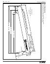
The live sound console shall be constructed in a modular fashion and be
housed in a steel frame with molded plastic side panel/carrying handles.
The console shall be black with white labeling and utilize XLR lighting
device connectors. The console shall have an XLR talkback mic connector
and a headphone jack. These shall be located beneath the far right side of
the armrest.
All microphone inputs shall be electronically balanced and accessed via 3-
pin XLR connectors and have an EIN of -129 dBm. All line inputs shall be
electronically balanced and accessed via 1/4" TRS jacks. The insert points
shall be via 1/4" TRS jacks.
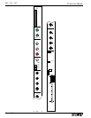
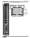
Each input channel shall have: a +48 volt phantom power switch, a -15 dB
mic pad switch, a 80Hz high pass filter switch, and 4-band fixed EQ
(80Hz, 300Hz, 2.7kHz, 10kHz) with an EQ In switch. Each input channel
shall also have: a FET controlled (10 millisecond ramp) mute switch with
LED, sub-group assignment switches, a L/R assignment switch, a dedicat-
ed mono assignment switch, a dynamic signal present LED and peak LED,
a PFL switch, and a 100mm long throw fader. Each input channel shall
have eight auxiliary sends which shall be controlled via six knobs and
three switches.The aux sends shall have a pre/post fader switch for every
four sends. The aux sends shall be selectable pre or post fader.
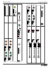
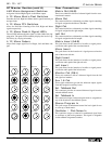
The console shall be available in four or eight bus configurations. Each
group module shall have a ten-segment LED meter array. The effect return
section of each group module shall have a gain control, a two-band fixed
EQ, sub-group assignment switches, a L/R assignment switch, a dedicated
mono assignment switch, two aux send controls, a pan control, a level con-
trol, a dynamic signal present LED and peak LED, and a PFL switch. The
remainder of the group module shall have a pan control, an FET controlled
(10 millisecond ramp) mute switch with LED, assignment switches for:
mono and L/R. A PFL switch, dynamic signal present LED and peak LED,
and a 100mm long throw fader shall also be provided on the group mod-
ule.
The master section shall be four modules in width and have the following
features: eight aux master controls with associated AFL switches, a
100mm long throw fader for each of the three master outputs and a com-
prehensive talkback system.
The power supply shall be housed in a 14 ga. steel chassis that shall occu-
py two 19" rack spaces. The power supply shall have the ability to be
daisy-chained to additional power supplies to provide a fail-safe operating
environment. Connection of two or more power supplies shall not require
additional interface hardware other than the provided cable.
The live sound console shall be: the Crest Audio Century SP.
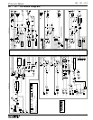
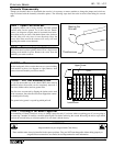
Four Subgroup 16, 24, 32, 36, 44, or 56 inputs
Eight Subgroup 12, 20, 28, 32, 40, or 52 inputs
Optional stereo input modules and matrix modules are available.
Configurations
SP Consoles are available in the following configurations:
Frequency Response
+0.0, -0.5dB, 20Hz to 20 kHz (referenced to 1kHz)
Total Harmonic Distortion
Mic input to Group output
20Hz to 20 kHz at +15dBu <0.01%
Noise (22Hz to 22kHz)
Mic EIN -129 dBu
Mix Bus Output Noise (20 ch routed) - 80 dBu
Aux Bus Output Noise (20 ch routed) - 80 dBu
Crosstalk (Measured at 1kHz)
Channel Mute >102 dB
Channel Fader Attenuation > 96 dB
Channel Routing > 85 dB
Channel Aux Send Attenuation > 93 dB
Input/Output Impedances
Mic Input 4kΩ balanced
Line Input >10kΩ balanced
Outputs 140Ω balanced
Input/Output Levels (0VU = +4 dBu, 1.23V RMS)
Mic Input Sensitivity + 4 to -62 dBu
Line Input Sensitivity + 12 to -38 dBu
Input Insertion Point Level + 4 dBu
Output Insertion Point Level - 2 dBu
Nominal Output Level + 4 dBu
Maximum Balanced Output Level +28 dBu