


SP / TC / GT
PAGE 3
CENTURY SERIES
1
2
3
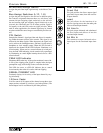
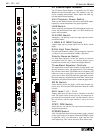
PIN 1 = GROUND
PIN 2 = POSITIVE
PIN 3 = NEGATIVE
OUTPUT XLR
INPUT XLR
PIN 3
PIN 1
PIN 2
PIN 3
PIN 2
PIN 1
TIP - POSITIVE
RING - NEGATIVE
SLEEVE - GROUND
INPUT
TIP - SEND
RING - RETURN
SLEEVE - GROUND
INSERT
TIP - POSITIVE
RING - GROUND
SLEEVE - GROUND
OUTPUT
Input Plug Polarities Insert Plug Polarities
Output Plug Polarity - TRS
TIP - POSITIVE
SLEEVE - GROUND
OUTPUT
Output Plug Polarity - Tip/Sleeve
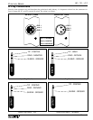
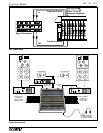
Wiring Conventions
Since the same connectors are used throughout the professional audio industry, it is important to know how the connectors for
Crest’s Century SP, TC, and GT consoles are wired. The wiring is as follows.