6 Pelco Manual C914M (7/96)
5.4 ANTENNA ALIGNMENT
NOTE: This section applies only to the
WLV2000 wireless receiver.
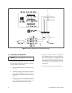
1. Connect a high impedance voltmeter to the RSSI
(Received Signal Strength Indication) test points
on the bottom of the enclosure:
a. Set the voltmeter on a low-volt DC scale (3 or
10 volts).
b. Connect the negative lead from the voltmeter
to the flat-head Phillips screw on the left on
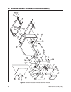
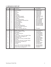
the bottom of the enclosure (part of item I in
Figure 6).
c. Connect the positive lead from the voltmeter
to the Phillips screw to the right of the screw
where you connected the negative lead.
d. Adjust the enclosure until the voltmeter indi-
cates minimum voltage (strongest RSSI sig-
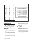
nal). Refer to Figure 5 as a guideline to see
how the voltage changes with distance. The
meter reading will vary depending on the ob-
stacles between antennas and the types of an-
tennas used.
e. Tighten all screws on the mounting bracket.
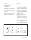
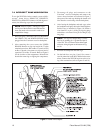
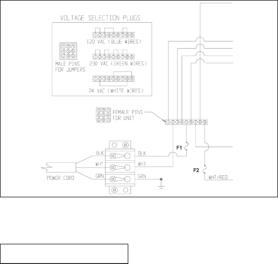
Figure 4. Power Connections (Outdoor Models Only)


