10 Pelco Manual C914M (7/96)
7.0 INTERCEPT
®
DOME MODIFICATION
To use the WLV500 wireless control system with In-
tercept
®
dome drives DD08CXX, DD08EXX,
DD14CXX, or DD14EXX (domes with 360 degree ro-
tation), the following steps must be performed:
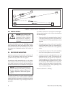
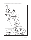
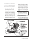
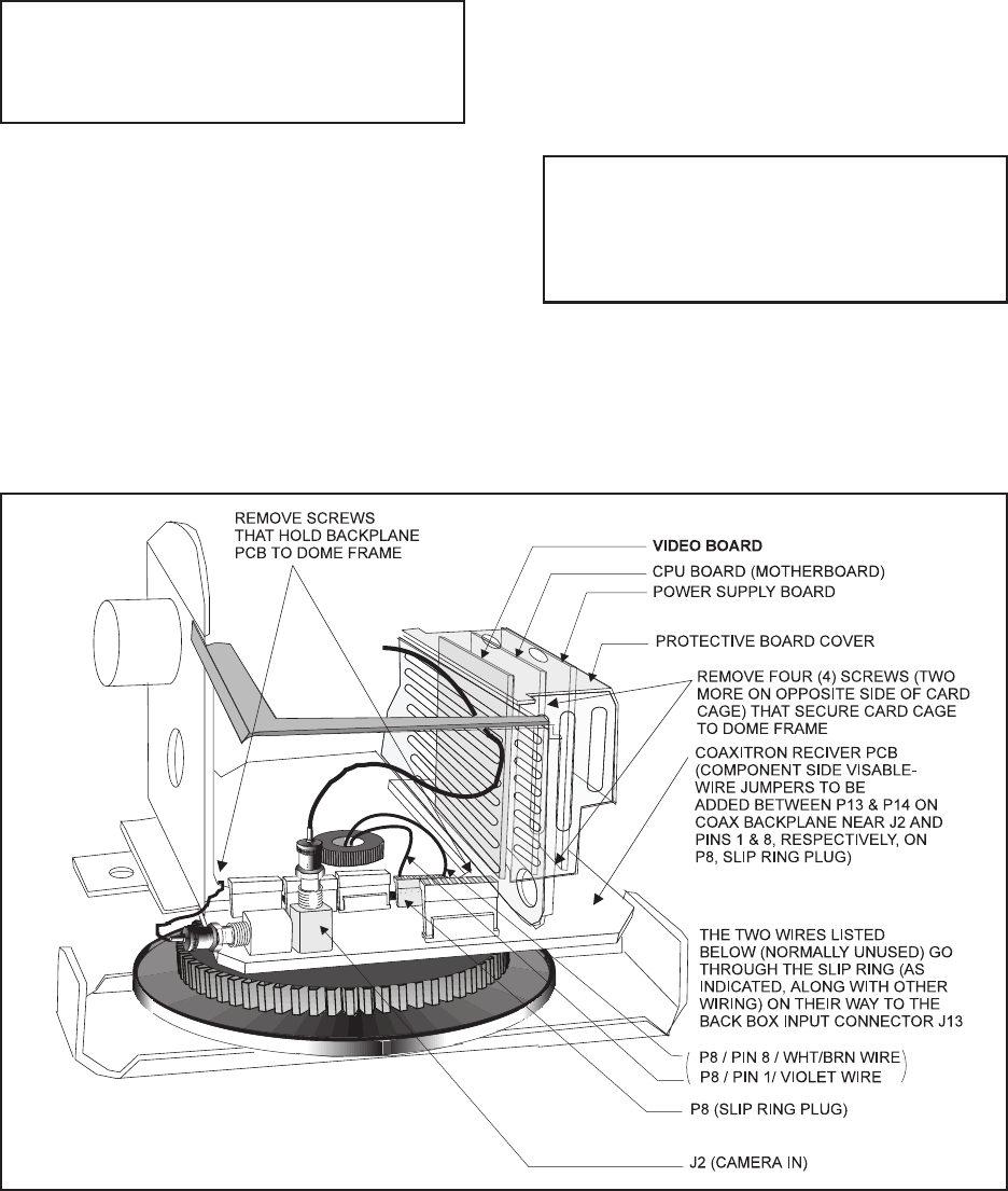
NOTE: Refer to Figure 7, which gives a gen-
eral layout of the dome drive and indicates the
items that need to be accessed in order to ac-
complish the change.
1. Refer to Figure 7 and remove the cover that houses
the VIDEO, CPU and POWER SUPPLY boards
plugged into the Coaxitron
®
receiver backplane.
2. After removing the cover, extract the VIDEO
BOARD. Remove or clip one lead of the 75-ohm
termination resistor: R26 on Rev. F boards or R20
on Rev. G boards. Also remove or clip one lead of
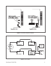
capacitor C56 on Rev. G boards. Refer to Figure 8
for the location of the components. Reinstall the
board after removing or clipping the components.
3. Disconnect all plugs and connectors to the
Coaxitron
®
receiver backplane and remove the
screws whose locations are indicated in Figure 7
(that part of the card cage holding the boards will
also detach as a unit along with the backplane).
4. After freeing the backplane and card cage, orient
the backplane to display the back of the backplane.
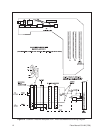
Solder wires as indicated in Figure 10: Solder a
wire from P13 to pin 1 of Plug 8 (slip ring plug)
and solder a wire from P14 to pin 8 of Plug 8 (slip
ring plug).
NOTE: This step has changed Plug 13 on the
batwing by making pin 11 ground and pin 19
video core. This is indicated in the abbreviated
reference wiring diagram at the bottom of Fig-
ure 10.
5. Reinstall the backplane and card cage.
6. On the back box, use pins 11 and 19 to create a
coaxial connection to the WLV2000 wireless trans-
mitter. Connect the WLV500 receiver to the exist-
ing video connection (refer to Figures 9 and 10).
Figure 7. Dome Drive Layout


