Pelco Manual C914M (7/96) 7
4. Check the power supply voltages for the wireless
transmitter and receiver. If the voltage at the trans-
mitter or receiver is less than 11 VDC, replace the
unit’s power supply.
5.5.2 Poor Picture
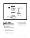
1. Refer to Section 4.0, “Antenna Location,” and
verify that the transmit and receive antennas are
positioned properly.
2. If you can not eliminate interference from other
signals, contact Pelco about replacing your wire-
less transmitter and receiver with units that oper-
ate on a different frequency.
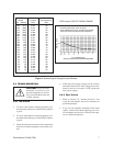
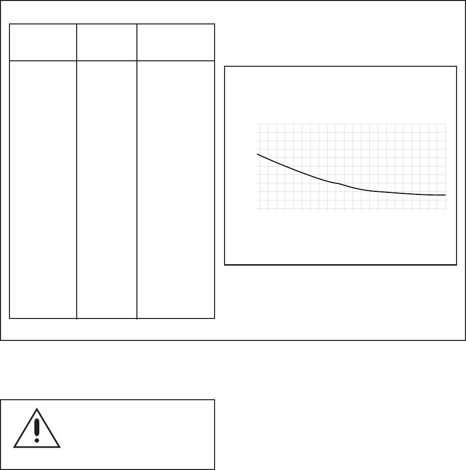
SYSTEM WLV2000 PATH LOSS
RANGE SYSTEM NO OBSTACLES
Feet (Meters) RSSI dBm
2,025 (617) 0.634 -96
1,600 (488) 0.579 -94
1,275 (389) 0.532 -92
1,015 (309) 0.489 -90
805 (245) 0.448 -88
640 (195) 0.412 -86
507 (155) 0.377 -84
403 (123) 0.347 -82
320 (98) 0.318 -80
255 (78) 0.292 -78
202 (62) 0.269 -76
160 (49) 0.248 -74
128 (39) 0.229 -72
101 (31) 0.214 -70
80 (24) 0.200 -68
64 (20) 0.188 -66
51 (16) 0.179 -64
40 (12) 0.173 -62
32 (10) 0.170 -60
25 (8) 0.168 -58
20 (6) 0.166 -56
16 (5) 0.165 -54
13 (4) 0.164 -52
0
0.5
1
2025
1275
640
320
160
80
40
20
L.O.S. RANGE (Feet)
WITH NO OBSTACLES BETWEEN ANTENNAS
RSSI (DC Volts)
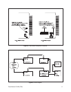
RSSI versus LOSS-OF-SIGNAL RANGE
WLV2000 WIRELESS VIDEO SYSTEM
WITH OMNIDIRECTIONAL TRANSMIT ANTENNA
AND HIGH GAIN LINEAR RECEIVE ANTENNA
5.5 TROUBLESHOOTING
CAUTION: Do not service the
transmitter or receiver. If you
open the transmitter or receiver
unit, you will break the seals and
void the warranty.
5.5.1 No Picture
1. To verify if the camera is operating properly, con-
nect the camera directly to a monitor that you know
is good.
2. To verify if the monitor is operating properly, con-
nect the monitor directly to a camera that you know
is good.
3. Check the cables between the wireless transmitter
and receiver and the equipment to which they con-
nect.
Figure 5. Antenna Signal Strength versus Distance


