Pelco Manual C914M (7/96) 13
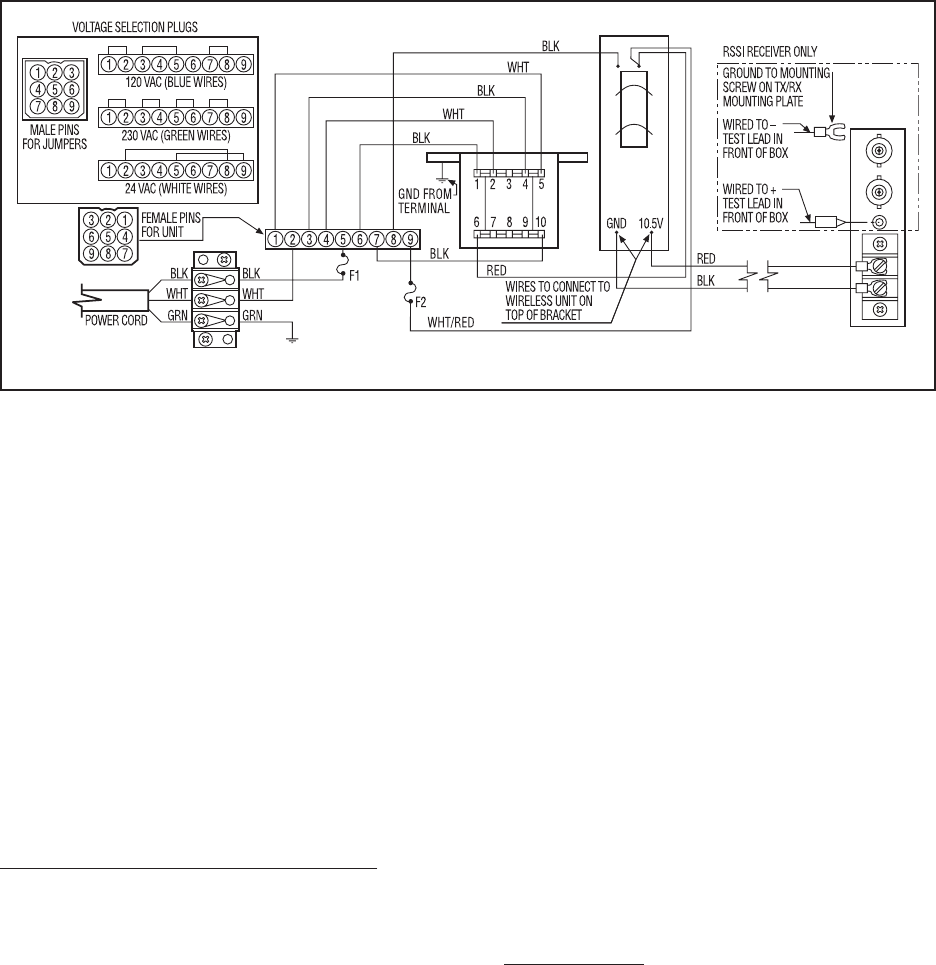
8.0 WIRING DIAGRAM
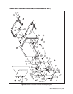
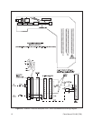
NOTE: Output voltage is 15 VDC, not 10.5
Figure 11. Outdoor Enclosure Wiring Diagram
9.0 MAINTENANCE
In cold, wet areas periodically visit the transmitter and
receiver sites to prevent the buildup of snow and ice on
the enclosures. A buildup of ice and snow will severely
attenuate the microwave signals, producing snow in the
picture. If the buildup is heavy enough, the system will
stop working.
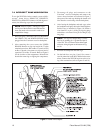
The enclosure has two one-quarter ampere slow-blow
fuses. Fuse F1 protects the input power (24, 120, or
230 VAC). Fuse F2 is for 24 VAC operation only. Re-
fer to Figure 4. To order replacement fuses, specify the
part number FUS1/4SB.
10.0 SPECIFICATIONS
GENERAL (WLV500 AND WLV2000)
Power Input: 24, 120, or 230 VAC
Operating Distance: 2,000 feet (609.6 m) line-of-
sight maximum range
Construction
Enclosure: Fiberglass box with NEMA
4X rating
Transmitter/
Receiver: Aluminum
IEC 144 Rating: IP66
Dimensions: 4.3" H x 11.5" L x 9.5" W
(10.92 x 29.21 x 24.13 cm)
Cable Entry: One (1) gland for power cord
Two (2) glands for video and
audio coaxial cables
Locking Method: Latches with holes for pad-
locks
Weight (including wireless transmitter or receiver)
WLV500 Trans: 9.5 lbs (4.31 kg)
WLV2000 Trans: 9.5 lbs (4.31 kg)
WLV500 Receiver 10.2 lbs (4.63 kg)
WLV2000 Receiver 10.4 lbs (4.72 kg)
Shipping (all units): 47.25 lbs (21.43 kg)
Operating
Temperature: -4° to 149° F (-20° to 65° C)
Storage
Temperature: -58° to 185° F (-50° to 85° C)
Humidity: 90% non-condensing
ELECTRICAL
DATA (WLV500)
Format: NRZ
Pulse Width: 1 microsecond.
Duty Cycle: 50%
Level (Video
Compatible): 1 V p-p


