2 Pelco Manual C914M (7/96)
2.0 SCOPE
This manual covers the installation of the WLV2500
Series of outdoor wireless systems.
3.0 DESCRIPTION
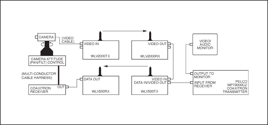
To make a WLV2500 system, a WLV500 control sys-
tem is combined with a WLV200 video transmission
system (refer to Figure 1).
The wireless control systems of the WLV500 Series
provide wireless remote control of camera positioning
and zoom functions.
The wireless video transmission systems of the
WLV2000 Series provide wireless distribution of a
single channel of a full-motion color video and audio
signal. The systems are compatible with all RS-170A
(NTSC) camera and video monitor systems.
Figure 1. Typical WLV500 Control Link and WLV2000 Video Link Configuration
3.1 MODELS
WLV2500KTE-1 - Consists of the following:
1. WLV500KTE-1L - Coaxitron
®
-control transmitter
and receiver operating at 2481 MHz. Includes
power supplies and directional antennas that are
left-hand circularity polarized (LHCP). Receive an-
tenna has 11 dBi of gain. Installed in NEMA-rated
enclosures with selectable voltage input.
2. WLV2000KTE-1R - Transmitter and receiver op-
erating at 2421.5 MHz. Includes power supplies
and directional antennas that are right-hand circu-
larity polarized (RHCP). Receive antenna has 11
dBi of gain. Installed in NEMA-rated enclosures
with selectable voltage input.
WLV2500KTE-3 - Consists of the following:
1. WLV500KTE-3R - Coaxitron
®
-control transmit-
ter and receiver operating at 2402 MHz. Includes
power supplies and directional antennas that are
right-hand circularity polarized (RHCP). Receive
antenna has 11 dBi of gain. Installed in NEMA-
rated enclosures with selectable voltage input.
2. WLV2000KTE-3L - Transmitter and receiver op-
erating at 2461.5 MHz. Includes power supplies
and directional antennas that are left-hand circu-
larity polarized (LHCP). Receive antenna has 11
dBi of gain. Installed in NEMA-rated enclosures
with selectable voltage input.


