Pelco Manual C914M (7/96) 3
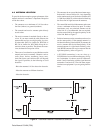
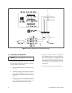
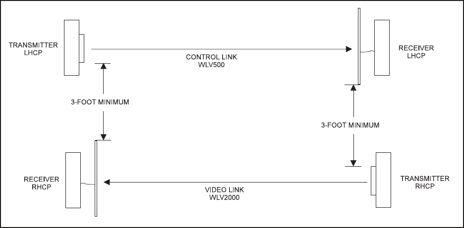
Figure 2. Transmitter-Receiver Placement at Same Site
4.0 ANTENNA LOCATION
To provide the best reception, proper placement of the
transmit and receive antennas is important. Reception
will be best when:
• The antennas are a minimum of 8-10 feet above
the floor (indoors) or ground (outdoors).
• The transmit and receive antennas point directly
at each other.
• The receive antenna is attached directly to the re-
ceiver. If you must extend the cable between the
antenna and receiver, use a high-quality, low-loss,
50-ohm cable (RG-8 or similar for WLV500, or
RG-316 or similar for WLV2000). Keep the ex-
tension as short as possible. The shorter the exten-
sion, the better the reception will be.
• There are as few obstacles as possible between the
transmit and receive antennas. Obstacles such as
walls, floors, shelves, machinery, boxes, trees,
chain link fences, and vehicle traffic will degrade
the signal. If possible, do the following to avoid
obstacles:
- Raise the antennas 8-10 feet above the obstacles.
- Move the antennas to different locations.
- Move the obstacles.
• The antennas do not exceed their maximum range.
Indoors this is about 300 feet (91.4 m), depending
on the number and type of obstacles. Outdoors this
is 2,000 feet (609.6 m) with no obstacles blocking
the direct line of sight between the antennas.
• The control link and video link antennas at the same
site are a minimum of three feet apart. To reduce
interference, only use polarized antennas on the
video link. It is recommended, but not required,
that the control link be the opposite polarity of the
video link. Refer to Figure 2.
• Polarized antennas on the transmitter and receiver
are the same polarity. If the transmit antenna is a
left-hand circularity polarized (LHCP) antenna, the
receive antenna must be left-hand polarity. If the
transmit antenna is a right-hand circularity polar-
ized (RCHP) antenna, the receive antenna must be
right-hand polarity (refer to Figure 2).
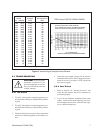
•A WLV2000 transmitter is not too close to a
WLV2000 receiver on a different frequency. In Fig-
ure 3, transmitter 1 is closer to receiver 2 than trans-
mitter 2 and is interfering with the signal between
transmitter 2 and receiver 2. Provide more separa-
tion between equipment if you are getting interfer-
ence.


