LIST OF ILLUSTRATIONS
Figure Page
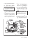
1Typical WLV500 Control Link and WLV2000 Video Link Configuration............................................2
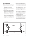
2Transmitter-Receiver Placement at Same Site ................................................................................3
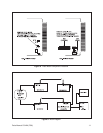
3 Multiple System Interference ...........................................................................................................4
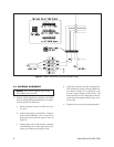
4 Power Connections (Outdoor Models Only) ....................................................................................6
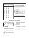
5 Antenna Signal Strength versus Distance .......................................................................................7
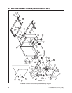
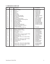
6 Outdoor Enclosure Exploded Assembly Diagram ...........................................................................8
7 Dome Drive Layout ........................................................................................................................10
8 Video Board Component Locations ..............................................................................................11
9 Block Diagram ...............................................................................................................................11
10 Coaxitron
®
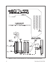
Receiver Backplane PCB - Wire Lead Additions and Wiring Diagram ........................12
11 Outdoor Enclosure Wiring Diagram...............................................................................................13
Pelco Manual C914M (7/96) iii
LIST OF TABLES
Table Page
AVideo Coaxial Cable Wiring Distances ............................................................................................5
REVISION HISTORY
Manual # Date Comments
C914M 7/96 Original manual.
8/96 Revised Section 7.0 and Figure 8 to include Rev. G of video board.
11/96 Revised Figure 6 per ECO 96-284. Added Section 8.0, “Wiring Diagram.”


