


7
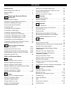
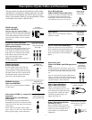
Descriptions of Jacks, Cables, and Connectors
TUNER
V
G
S-VIDEO
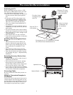
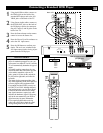
This page contains descriptions and illustrations of jacks, cables,
and connectors you might use in making connections. The cables
and connectors are not supplied with your TV, but you can pur-
chase at your electronics dealer. Or you can order them by calling
our Customer Care Center at 1-800-531-0039.
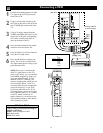
Antenna RF Jack
Cable Used: RF
Coaxial (75Ω)
Push-on
Type Cable
Screw-on
Type Cable
Signal Splitter
Cables Used: RF
Coaxial (75Ω)
Video (Composite) Jack
Cable Used:Video with
RCA-type Phono Plugs
Or
S-VIDEO Jack
Cable Used: S-Video
Pr Pb Y
Component Video Jacks
Cables Used: Component
Video with RCA-type
Phono Plugs
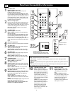
DVI
DVI-D Jack
Cables Used: DVI-D
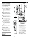
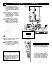
DVI-D Input Jack
Cable used: DVI-D
This jack works only with DVI TMDS
(Transition Minimized Differential Signaling)
digital video. Allows encrypted transmissions
of uncompressed digital content. The DVI-D
jack used in this product is not for computer
connections.
Component Video Input Jacks
Cables used: component video with
RCA-type phono plugs
Allow you to connect accessory devices such
as DVD players. Separating the video into
three signals, these inputs provide excellent
quality. Be sure to connect the left and right
audio cables, because the Y, Pb, Pr jacks
receive only the picture signal.
NOTE: See the “Helpful Hint” on page 13
for more information.
S-Video Input Jacks
Cable used: S-Video
Provide a higher quality picture than the
Video (composite) jacks because the color
part of the picture is separated from the black
and white portion. Be sure to connect the left
and right audio cables, because the S-Video
jacks receive only the picture signal.
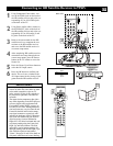
RGB+HV
VGA/HD15 Jack
Cable Used: HD DB15
RGB+HV Input Jack
Cable used: HD DB15
Allows you to connect equipment with RGB
or VGA output.
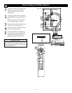
Video (called “CVBS” or “composite”)
Input Jacks
Cable used:Video with RCA-type
phono plugs
Provide better picture performance than the
antenna RF input. Be sure to connect the audio
cables, because the video jacks receive only the
picture signal.
Your TV also has a monitor output (“MON
OUT”) video (“V”) jack. Use a video cable with
RCA-type phone plugs to make connections.
Tuner (RF) Input Jack
Cables used: RF coaxial cable (75Ω)
Allows you to connect an antenna, cable TV,
or components having RF outputs to the
antenna input on the TV. RF coaxial cables
are available in push-on or screw-on type.
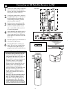
Audio Input Jacks
Cables used:Audio with RCA-type phono
plugs
Provide sound for the video inputs. If your acces-
sory device has only one output for audio, connect
it to the left (color coded white) audio jack on the
TV.
Your TV also has monitor output (“MON OUT”)
audio (“L” and “R”) jacks and a subwoofer output
(“SUB OUT”) jack. Use an audio cable with RCA-
type phone plugs to make connections.
Audio Jacks
Cables Used:
Audio with RCA-
type Phono Plugs
RL
Signal Splitter
Allows you to route an antenna or cable TV
signal to two inputs.
3.5mm Stereo Mini Phone
Plug to RCA Jack Adapter
Allows a connection between the
3.5mm stereo audio out jack on a com-
puter and the left and right audio inputs
on the television. Connect A/V cables
with RCA-type phono plugs to the
adapter, then to the TV.
3.5mm Stereo Mini Phone Plug
to RCA Jack Adapter
300- to 75-ohm
Twin-lead Adapter
300- to 75-ohm Twin-lead Adapter
Accepts twin-lead wires from an antenna and
allows connection to the antenna input on the
TV. If your antenna is already equipped with
an RF coaxial cable you will not need this
adapter.
TUNER
Center Channel Amp Speaker
Terminals (+ and –)
Allow a connection from a surround
sound receiver. Set the EXT/INT switch
to EXT to use the TV speakers as the
center speakers in a surround sound
arrangement.
Center Channel Amp Speaker
Terminals (for the connection
of speaker wires)
+
_
INT
EXT