


8
Panel Jack Compatibility Information
7
1
2
3
4
5
6
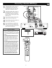
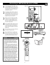
DVI
G
S-VIDEO
G
S-VIDEO
RLV
RL
RL
RL
V
Pr Pb Y
RL
RL
Pr Pb Y
Pr Pb Y
RL
V
STANDARD/
HD INPUTS
STANDARD/
HD INPUTS
TUNER
RGB+HV
AV5 AV6
AV1MONSUB OUT AV2AV3AV4
OUT
SERVICE 1
2
C
10
11
CENTER CHANNEL AMP INPUT
+
_
INT
EXT
5
8
9
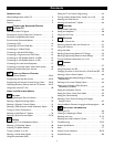
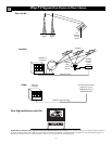
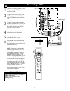
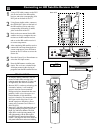
Speaker Terminals and
EXT(ernal)/INT(ernal) Speaker Switch
Located on the Back Left Side of the TV
Jack Panel Located
on the Left Side of
the TV
CENTER CHANNEL AMP
INPUT Click-fit Terminals
Provides speaker-wire input termi-
nals for connection of an external
home-cinema surround-sound sys-
tem amplifier. For this use, set the
switch to “EXT,” and the TV
speakers become the center speak-
ers for the home-cinema surround-
sound system.
NOTE: If no audio is heard from
the set, check to make sure the
Center Channel Amp switch is in
the INT position. This switch
should be in the EXT position
only when an external center
channel input is connected to the
Click-fit Terminals.
10
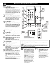
SIDE JACK PANEL
Signals accepted: NTSC (480i).
Inputs available: S-Video (Y/C)
and CVBS, plus audio left and
right.
Output available: Headphone.
Only one of the inputs can be used
at a time. Select the Side source,
and the TV detects the input to
which you have connected.
Connections must be made to the
audio inputs for sound.
11
1
AV 1 Input Jacks
Signals accepted: NTSC (480i).
Inputs available: YPbPr, S-Video (Y/C), and
CVBS, plus audio left and right.
Use only one of the video signal inputs at a time.
If you should forget and have more than one type of
signal connected, the set will automatically show the
one of better quality: CVBS—good, S-Video—bet-
ter, and YPbPr—best. For sound, connections must
be made to the AV1 audio inputs.
2
MON OUT Output Jacks
Provide video and audio output signals from all TV
when those sources are being viewed on the main
screen. Output from the audio L/R jacks is at a fixed
volume level; changing the TV volume does not
affect them. Adjust the volume at your external
home cinema system.
3
AV 2 Input Jacks
Signals accepted: NTSC (480i).
Inputs available: S-Video (Y/C) and CVBS, plus
audio left and right.
Use only one of the video signal inputs at a time.
If you should forget and have both types of signal
connected, the set will automatically show the
S-Video, since it is of better quality than CVBS. For
sound, connections must be made to the AV2 audio
inputs.
4
SUB OUT Output Jack
Provides a signal to an external powered subwoofer.
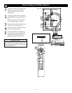
5
AV3 Input Jacks
Signals accepted: NTSC (480i), 480p, 720p, and
1080i, plus audio left and right.
Inputs available: YPbPr, plus audio. For sound,
connections must be made to the AV3 audio inputs.
6
AV4 Input Jacks
Signals accepted: NTSC (480i), 480p, 720p, and
1080i, plus audio left and right.
Inputs available: YPbPr, plus audio. For sound,
connections must be made to the AV4 audio inputs.
7
TUNER Input Jack
Signals accepted: RF modulated NTSC.
Inputs available: 75Ω RF coaxial.
8
AV5 Input Connectors
Signals accepted: NTSC (480i), 480p, 720p, 1080i,
and 1s1111111111111111111111111111111VGA plus
audio left and right.
Inputs available: RGB+HV. For sound, connec-
tions must be made to the AV5 audio inputs.
9
AV6 Input Connectors
Signals accepted: Digital only (TMDS [Transition
Minimized Differential Signaling] encoded, uncom-
pressed); DVI 480i, 480p, 720p, and 1080i, plus
audio left and right.
Inputs available: DVI TMDS, plus audio. For
sound, connections must be made to the AV6 audio
inputs.
Intended use of the input: digital set-top boxes and
inputs from other digital video devices.
NOTE: This DVI jack is not for computer con-
nections. VGA cannot be connected.
Definitions:
NTSC—National Television System Committee.
CVBS—labeled “V,” provides a small step up in quality from the Tuner (RF) input. Called
Composite Video.
S-Video (Y/C)—provides better picture quality than CVBS. Separates the signal into color and
brightness.
YPbPr—provides the best quality video signal. Called Component Video Input, the signal is
split into three parts, two color and one brightness.