


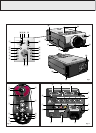
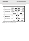

REMOTE CONTROL
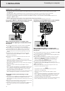
(fig. 2)
1 On / Off switch z / y
For switching the remote control as well as the projector
on and off.
Note:
The remote control will always use some power, even when
not in use. The remote control unit will automatically switch off
when not used for 30 minutes.
2
Tracking Ball
For manipulating the mouse cursor on the connected computer.
Notes:
– The Tracking Ball only functions when the provided USB
Mouse Receiver is connected to the USB port of a PC.
– The minimum system requirements for the USB Mouse
receiver are Windows 98 and/or Windows 2000 or higher.
– A cursor control requires the presence of data signal.
3
Mouse left and Mouse Right (-/--)
The mouse left/right buttons (-/--) on the remote control
function as the left and right mouse buttons of your PC,
only in case the provided USB Mouse receiver properly is
connected to the PC.
4 Cursor Control
To operate and navigate through the activated menu via
up/down and the left/right cursor buttons
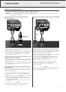
5 Auto sync
For activating the Auto sync operation in Data mode.
6 Input
For selecting in sequence the Data or Video signal as the
current projection source.
The button toggles between Data 1, Data 2 or Video signal.
7 Audio / Video - Mute
For muting the sound of the projector (or an externally
connected sound amplifier) and for muting the picture.
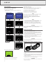
8 Lens
For selecting the optical lens adjustments Zoom, Focus,
Digital Keystone correction and Digital Image Shift (see
Note). The button toggles between the ZOOM-, FOCUS-,
KEYSTONE and DIGITAL SHIFT function.
Note:
Digital Image Shift feature can only be addressed while
being in the WIDE and NORMAL (WIDE) picture display
modes during video or DTV input. (See page 24 for details.)
9 OK
For action confirmation in the menu when the menu is on
the screen (activated)
0 D-Zoom
For addressing the D-Zoom function. The button toggles
between the digital magnification factors, x1, x2, x3, x4, x6
and x8.
! Menu
For activating and de-activating the On Screen Display
Menu
@ Back light
For switching on the button illumination.
The back-light will switch off automatically after 5 seconds.
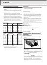
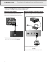
CONNECTIONS
(fig. 3)
A Data 1 in (15 pin)
Input socket for connecting to the Data out terminal of a
computer.
B Audio 1 in (3.5 mm stereo minijack)
Input socket for connecting to the Audio out terminal of a
computer or any other audio equipment.
C Data 2 in (15 pin)
Input socket for connecting to the Data out terminal of a
computer.
D Audio 2 in (3.5 mm stereo minijack)
Input socket for connecting to the Audio out terminal of a
computer or any other audio equipment.
E Data 1 in (BNC) (R (Pr), G/G sync (Y), B (Pb),
HD (C sync), VD)
Input sockets
for connecting Data 1
BNC connection.
F Data out (15 pin)
Output socket for connecting to the Data in terminal of another
data projector or data monitor.
G Audio out (3.5 mm stereo minijack)
Output socket for connecting to the Line Input sockets of an
amplifier or stereo system.
H AC socket
For connecting the projector to the powercord.
I S-Video in (4 pin mini DIN)
Input socket for connecting to any other Audio Video
equipment equipped with a S-Video output socket.
J RS-232C port (9-pin mini-DIN)
For connecting a computer to the projector with a RS-232C
cable (optional). The computer can be used in this way to
control the projector.
K Video in (RCA)
Input socket for connecting to any other Audio Video
equipment equipped with a Video output socket. (PAL, NTSC,
SECAM).
L Audio in L/R (RCA)
Input sockets for connection to the AUDIO OUT sockets of a
video recorder (S-VHS, PAL, NTSC, SECAM).
M 15 pin/BNC switch
To switch between 15 pin or BNC Data 1 input.
8
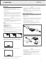
5. FUNCTIONAL OVERVIEW
See illustrations on page 4