


1999 Oct 12 11
Philips Semiconductors Product specification
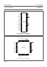
IC card interface TDA8002C
Logic circuitry
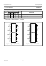
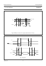
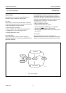
After power-up, the circuit has six possible states of
operation. Figure 9 shows the state diagram.
IDLE MODE
After reset, the circuit enters the idle mode. A minimum
number of functions in the circuit are active while waiting
for the microcontroller to start a session:
• All card contacts are inactive
• I/OUC, AUX1UC and AUX2UC are high-impedance
• Oscillator (XTAL) runs, delivering CLKOUT
• Voltage supervisor is active.
LOW-POWER MODE
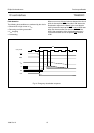
When pin MODE goes LOW, the circuit enters the
low-power (sleep) mode. As long as pin MODE is LOW no
activation is possible.
If pin MODE goes LOW in the active mode, a normal
deactivation sequence is performed before entering the
low-power mode. When pin MODE goes HIGH, the circuit
enters the normal operating mode after a delay of at least
6 ms (96 cycles of CLKOUT). During this time the
CLKOUT remains at 16 kHz.
• All card contacts are inactive
• Oscillator (XTAL) does not operate
• The V
DD
supervisor, ALARM output, card presence
detection and OFF output remain functional
• Internal oscillator is slowed to 32 kHz, providing 16 kHz
on CLKOUT.
ACTIVE MODE
When the activation sequence is completed, the
TDA8002C will be in the active mode. Data is exchanged
between the card and the microcontroller via the I/O lines.
Fig.9 State diagram.
handbook, full pagewidth
MGE735
POWER
OFF
ACTIVE
MODE
LOW-POWER
MODE
IDLE
MODE
FAULT
ACTIVATION
DEACTIVATION