


1999 Oct 12 18
Philips Semiconductors Product specification
IC card interface TDA8002C
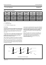
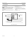
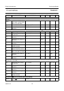
Data lines
GENERAL
t
d(edge)
delay between falling edge
of I/O, AUX1, AUX2, I/OUC,
AUX1UC and AUX2UC
−−1 µs
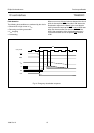
t
r
, t
f
rise and fall times C
i
=C
o
=30pF −−0.5 µs
f
I/O(max)
maximum frequency on
data lines
−−200 kHz
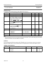
DATA LINES I/O, AUX1 AND AUX2 (WITH 10 KΩ PULL-UP RESISTOR CONNECTED TO V
CC
)
V
o
output voltage Idle and low-power modes 0 − 0.3 V
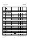
V
OH
HIGH-level output voltage
on data lines
I
OH
= −20 µA 0.8V
CC
− V
CC
V
V
OL
LOW-level output voltage on
data lines
I
I/O
=1mA −−0.4 V
V
IH
HIGH-level input voltage on
data lines
0.6V
CC
− V
CC
V
V
IL
LOW-level input voltage on
data lines
0 − 0.5 V
V
idle
voltage on data lines
outside a session
−−0.4 V
R
pu
internal pull-up resistance
between data lines and V
CC
81012kΩ
I
edge
current from data lines
when active pull-up is active
− 1 − mA
I
IL
LOW-level input current on
data lines
V
IL
= 0.4 V −−−600 µA
I
IH
HIGH-level input current on
data lines
V
IH
=V
CC
−−10 µA
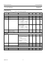
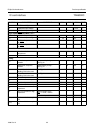
DATA LINES I/OUC, AUX1UC AND AUX2UC (WITH 20 KΩ PULL-UP RESISTOR CONNECTED TO V
DD
WHEN CS IS HIGH AND
100 KΩ WHEN CS IS LOW)
V
OH
HIGH-level output voltage
on data lines
I
OH
= −20 µAV
DD
− 1 − V
DD
+ 0.2 V
V
OL
LOW-level output voltage on
data lines
I
I/OUC
=1mA −−0.4 V
V
IH
HIGH-level input voltage on
data lines
0.7V
DD
− V
DD
V
V
IL
LOW-level input voltage on
data lines
0 − 0.3V
DD
V
Z
idle
impedance on data lines
outside a session
10 −− MΩ
ALARM and OFF when connected (open-drain outputs)
I
OH(OFF)
HIGH-level output current
on pin OFF
V
OH(OFF)
=5V −−5 µA
SYMBOL PARAMETER CONDITIONS MIN. TYP. MAX. UNIT