


- 9 -
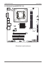
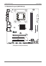
nVIDIA MCP73 Series Users Manual
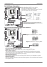
2.3 Installation of the CPU and CPU Cooler
Before installing the CPU, please comply with the following conditions:
1. Please make sure that the mainboard supports the CPU.
2. Please take note of the one indented corner of the CPU. If you install the CPU in the wrong
direction, the CPU will not insert properly. If this occurs, please change the insert direction
of the CPU.
3. Please add an even layer of heat sink paste between the CPU and CPU cooler.
4. Please make sure the CPU cooler is installed on the CPU prior to system use, otherwise
overheating and permanent damage of the CPU may occur.
5. Please set the CPU host frequency in accordance with the processor specications. It is not
recommended that the system bus frequency be set beyond hardware specications since
it does not meet the required standards for the peripherals. If you wish to set the frequen-
cy beyond the proper specications, please do so according to your hardware
specications including the CPU, graphics card, memory, hard drive, etc.
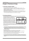
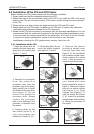
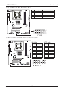
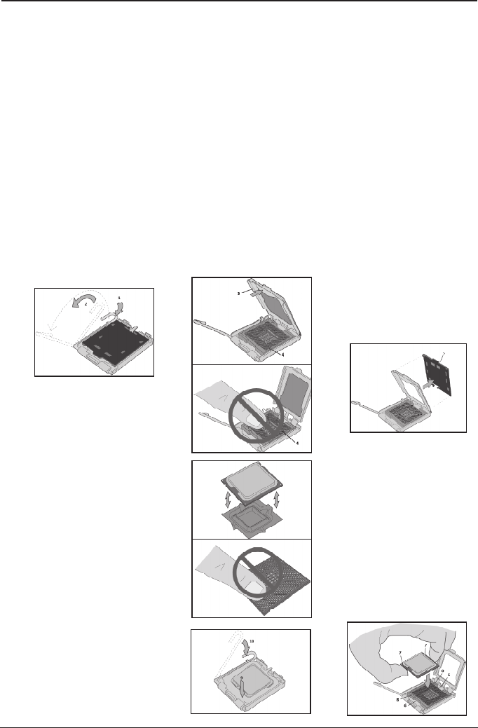
2.3.1 Installation of the CPU
1. Open the socket lever by
pushing the lever down and
away from the socket (see
Figure 1, 1 and 2).
2. Lift the load plate. Do not
touch the socket contacts
(see Figure 2, 3 and 4)
3. Remove the plastic
protective socket cover
from the load plate (see
Figure 3, 5). Do not discard
the protective socket cover.
Always replace the socket
cover if the processor is
removed from the socket.
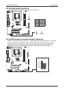
4. Remove the processor
f ro m t he p r ot e c ti v e
processor cover. Hold the
processor only at the edges,
being careful not to touch
the bottom of the processor
(see Figure 4). Do not
discard the protective
processor cover. Always
replace the processor
back to the package if the
processor is removed from
the socket.
5. Hold the processor with
your thumb and index
ngers oriented as shown in
Figure 5. Make sure ngers
align to the socket cutouts
(see Figure 5, 6). Align
notches (see Figure 5, 7)
with the socket see (Figure
5, 8). Lower the processor
straight down without tilting
or sliding the processor in
the socket.
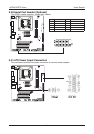
6. Pressing down on the
load plate (Figure 6, 9)
close and engage the
socket lever (Figure 6, 10).
Figure 1
Figure 2
Figure 3
Figure 4
Figure 6
Figure 5