


- 11 -
nVIDIA MCP73 Series Users Manual
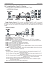
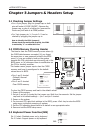
2.5 Connecting Peripheral Devices
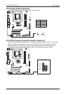
2.5.1 Floppy and IDE Disk Drive Connectors
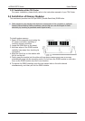
The FDD connector connects up to two oppy drives with a 34-wire, 2-connector oppy
cable.Connect the single end at the longer length of ribbon cable to the FDD on the board,
the two connectors on the other end to the oppy disk drives connector. Generally you need
only one oppy disk drive in your system.
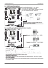
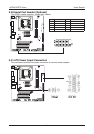
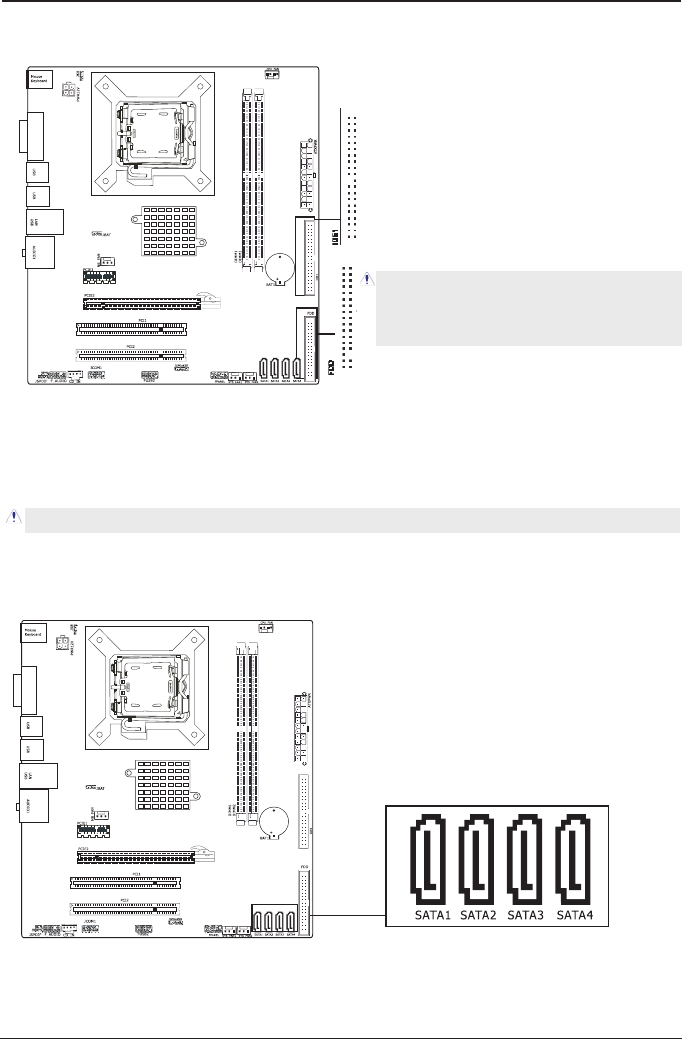
2.5.2 Serial ATA Connectors
Each SATA connector serves as one single channel to connect one SATA device by SATA
cable.
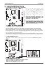
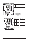
2.5.3 PCI and PCI Express slots
Install PCI Express X16 graphics card into slot “PCIE2”.
Install PCI Express X1 card into slot “PCIE1”.
Install PCI card into slots “PCI1” or “PCI2”.
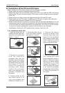
Each of the IDE port connects up to
two IDE drives at Ultra ATA 66/100/133
mode by one 40-pin, 80-conductor,and
3-connector Ultra ATA/66 ribbon cables.
Connect the single end (blue connector)
at the longer length of ribbon cable to
the IDE port of this board, the other two
ends (gray and black connector) at the
shorter length of the ribbon cable to the
connectors of your hard drives.
Make sure to congure the “Master” and “Slave”
relation before connecting two drives by one
single ribbon cable. The red line on the ribbon
cable must be aligned with pin-1 on both the IDE
port and the hard-drive connector.
The red line on the ribbon cable must be aligned with pin-1 on both the FDD port and the oppy connector.
V
G
A
V
G
A