


1of16
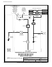
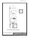
POWER WIRING INSTALLATION NOTES
111504
DESCRIPTION:
DATE:
DRAWING NO: SHEET:
REVISION:
B
164201535---5
Installation Information
A-11
Powerware
®
9390 UPS (40–80 kVA) Installation and Operation Manual S 164201535 Rev C
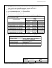
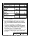
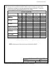
Table E. INPUT/OUTPUT Ratings & External Wiring Requirements for Powerware 9390---40
Units Rating 50/60 Hz
BasicUnitRatingat0.9laggingpFload
kVA
kW
40
36
40
36
Input and Bypass Input
Output
VOLTS
VOLTS
208
208
480
480
AC Input to UPS Rectifier (0.98 min. pF)
Full Load Current plus Battery Recharge Current
(3) Phases , (1) Ground
A
Amps 125 55
Minimum Conduc tor Siz e
Number per Phase
A
AWG or kcmil
(each)
2/0
(1)
4
(1)
AC Input to UPS Bypass
Full Load Current
(3) Phases, (1) Neutral---if required, (1) Ground
B
Amps 111 48
Minimum Conduc tor Siz e
Number per Phase
B
AWG or kcmil
(each)
2/0
(1)
4
(1)
DC Input from Battery to UPS
(1) Positive, (1) Negative
C
Vdc
Amps@ (2.0V/cell)
384---480
101
432---480
101
Minimum Conduc tor Siz e
Number per Pole
C
AWG or kcmil
(each)
1/0
(1)
1/0
(1)
AC Output to Critical Load
Full Load Current
(3) Phases, (1) Neutral---if required, (1) Ground
D
Amps 111 48
Minimum Conduc tor Siz e
Number per Phase
D
AWG or kcmil
(each)
2/0
(1)
4
(1)
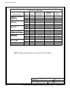
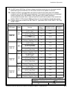
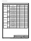
NOTE: Callout letters A, B, C,andD map to drawing 164201535---4, sheets 1 of 5,
3 of 5, 4 of 5, and 5 of 5.
Read and understand the following notes while planning and performing the installation:
1. Refer to national and local electrical codes for acceptable external wiring practices.
2. Material and labor for external wiring requirements are to be provided by designated
personnel.
3. For external wiring, use 90G C copper wire. See the appropriate information in Table E
through Table H. Wire sizes are based on using the specified breakers.
4. Wire ampacities are chosen from Table 310---16 of the NEC. Wire is 90GC specification.
5. The bypass feed into this equipment uses three or four wires. The rectifier f eed into t his
equipment uses three wires. The phases must be symmetrical about ground (i.e., from a
Wye s ource) for proper equipment operation. If the l oad requires a neutral, a bypass
source neutral must be p rovided. Do not bond the neutral to ground.
6. The UPS cabinet is shipped with a debris shield covering the ventilation grill on top of the
unit. Do not remove the debris shield until installation is complete. However, remove s hield
before operating the UPS. Once the debris shield is removed, d o not place objects o n
ventilation grill.
7. Refer to Section I of this manual for installation instructions.