


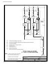
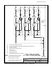
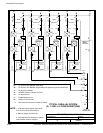

POWER WIRING INSTALLATION NOTES
111504
DESCRIPTION:
DATE:
DRAWING NO: SHEET:
REVISION:
B
164201535---5
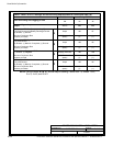
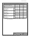
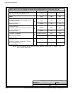
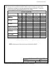
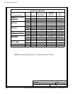
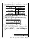
NOTE: Customer ground can be run in any conduit listed in Table K.
6of16
Installation Information
A-16
Powerware
®
9390 UPS (40–80 kVA) Installation and Operation Manual S 164201535 Rev C
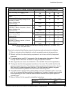
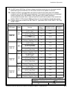
Table J. UPS Cabinet Power Cable Terminations Powerware 9390---40, 9390---50 9390---60,
and 9390---80 (480V/480V)
Terminal Function Terminal Function
Size of Pressure
Termination
Tightening
Torque
Nm (lb in)
Type
Screw
AC Input to UPS Rectifier
d
B
E6 Phase A 1 --- #14 --- 2/0
13.5 (120)
3/16 in. Hex
p
and Bypass
(
S
i
n
g
l
e
I
n
p
u
t
)
E7 Phase B 1 --- #14 --- 2/0
13.5 (120)
3/16 in. Hex
(
S
i
ng
l
e
I
nput
)
E8 Phase C 1 --- #14 --- 2/0
13.5 (120)
3/16 in. Hex
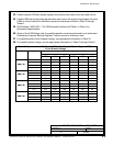
AC Input to UPS Rectifier
(
D
l
I
)
E1 Phase A 1 --- #14 --- 2/0 13.5 (120) 3/16 in. Hex
p
(Dual Input)
E2 Phase B 1 --- #14 --- 2/0 13.5 (120) 3/16 in. Hex
E3 Phase C 1 --- #14 --- 2/0 13.5 (120) 3/16 in. Hex
AC Input To Bypass
(
D
l
I
)
E6 Phase A 1 --- #14 --- 2/0
13.5 (120)
3/16 in. Hex
p
y
p
(Dual Input)
E7 Phase B 1 --- #14 --- 2/0
13.5 (120)
3/16 in. Hex
E8 Phase C 1 --- #14 --- 2/0
13.5 (120)
3/16 in. Hex
Single Feed Jumper from
R
i
f
i
I
T
i
l
— Phase A N/A 5.6 (50) 1/4–20 Hex Nut
g
p
Rectifier Input Terminals
t
o
B
y
p
a
s
s
I
n
p
u
t
T
e
r
m
i
n
a
l
s
— Phase B N/A 5.6 (50) 1/4–20 Hex Nut
to
B
ypass
I
nput
T
erm
i
na
l
s
— Phase C N/A 5.6 (50) 1/4–20 Hex Nut
AC Output to
C
i
i
l
L
d
E9 Phase A 1 --- #14 --- 2/0
13.5 (120)
3/16 in. Hex
p
Critical Load
E10 Phase B 1 --- #14 --- 2/0
13.5 (120)
3/16 in. Hex
E11 Phase C 1 --- #14 --- 2/0
13.5 (120)
3/16 in. Hex
DC Input from
B
U
P
S
E4 Positive 1 --- #6 --- 500 kcmil
56.5 (500)
1/2 in. Hex
p
Battery to UPS
E5 Negative 1 --- #6 --- 500 kcmil
56.5 (500)
1/2 in. Hex
Input and Output Neutral E12 Neutral 4 --- #14 --- 1/0 5.6 (50) Slotted
Customer Ground Ground Ground 8 --- #14 --- 1/0 5.6 (50) Slotted