


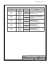
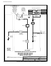
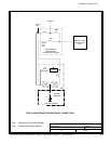
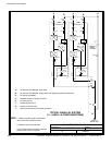
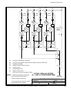
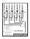
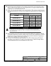
POWER WIRING INSTALLATION NOTES
111504
DESCRIPTION:
DATE:
DRAWING NO: SHEET:
REVISION:
B
164201535---5 2 of 16
Installation Information
A-12
Powerware
®
9390 UPS (40–80 kVA) Installation and Operation Manual S 164201535 Rev C
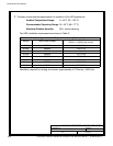
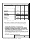
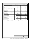
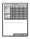
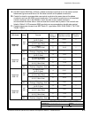
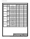
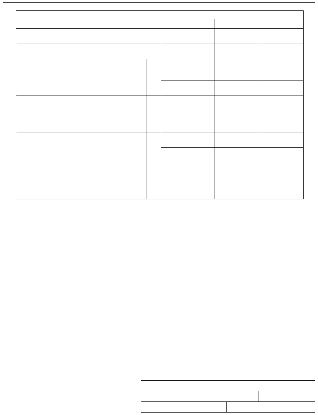
Table F. INPUT/OUTPUT Ratings & External Wiring Requirements for Powerware 9390---50
Units Rating 50/60 Hz
BasicUnitRatingat0.9laggingpFload
kVA
kW
50
45
50
45
Input and Bypass Input
Output
VOLTS
VOLTS
208
208
480
480
AC Input to UPS Rectifier (0.98 min. pF)
Full Load Current plus Battery Recharge Current
(3) Phases, (1) Ground
A
Amps 155 67
Minimum Conductor Size
Number per Phase
A
AWG or kcmil
(each)
4/0
(1)
2
(1)
AC Input to UPS Bypass
Full Load Current
(3) Phases, (1) Neutral---if required, (1) Ground
B
Amps 139 60
Minimum Conductor Size
Number per Phase
B
AWG or kcmil
(each)
4/0
(1)
2
(1)
DC Input from Battery to UPS
(1) Positive, (1) Negative
C
Vdc
Amps@ (2.0V/cell)
384---480
126
432---480
126
Minimum Conductor Size
Number per Pole
C
AWG or kcmil
(each)
1/0
(1)
1/0
(1)
AC Output to Critical Load
Full Load Current
(3) Phases, (1) Neutral---if required, (1) Ground
D
Amps 139 60
Minimum Conductor Size
Number per Phase
D
AWG or kcmil
(each)
4/0
(1)
2
(1)
NOTE: Callout letters A, B, C,andD map to drawing 164201535---4, sheets 1 of 5,
3 of 5, 4 of 5, and 5 of 5.