


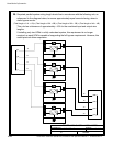
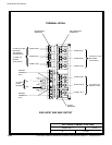
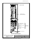

POWER WIRING INSTALLATION NOTES
093004
DESCRIPTION:
DATE:
DRAWING NO: SHEET:
REVISION:
B
164201535---5
14 of 16
Installation Information
A-24
Powerware
®
9390 UPS (40–80 kVA) Installation and Operation Manual S 164201535 Rev C
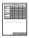
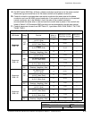
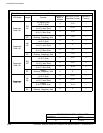
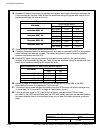
Table R. INPUT/OUTPUT Ratings for Powerware 9390---60 Parallel System
Configuration Units Rating 50/60 Hz
BasicUnitRatingat0.9laggingpFload
kVA
kW
60
54
60
54
Input and Bypass Input
Output
VOLTS
VOLTS
208
208
480
480
A
l
l
AC Input from UPM
Full L oad Current for each Module
(3) Phases, (1) Neutral, (1) Ground
D
Amps 167 72
A
l
l
Minimum Conductor Size for each Module
NumberperPhaseforeachModule
D
AWG or
kcmil
(each)
See Table E through
TableHforwiresize.
1
+
1
AC Input to Tie Cabinet Bypass (optional)
Full Load Current
(3) Phases, (1) Neutral---if required, (1) Ground
F
Amps 167 72
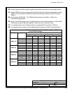
1+1
AC Output to Critical Load
Full L oad Current
(3) Phases, (1) N eutral, (1) Ground
G
Amps 167 72
2+0
a
n
d
AC Input to Tie Cabinet Bypass (optional)
Full Load Current
(3) Phases, (1) Neutral---if required, (1) Ground
F
Amps 334 144
an
d
2+1
AC Output to Critical Load
F ull Load Current
(3) Phases, (1) N eutral, (1) Ground
G
Amps 334 144
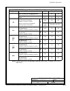
3+0
a
n
d
AC Input to Tie Cabinet Bypass (optional)
Full Load Current
(3) Phases, (1) Neutral---if required, (1) Ground
F
Amps 501 216
an
d
3+1
AC Output to Critical Load
F ull Load Current
(3) Phases, (1) N eutral, (1) Ground
G
Amps 501 216
4
+
0
AC Input to Tie Cabinet Bypass (optional)
Full Load Current
(3) Phases, (1) Neutral---if required, (1) Ground
F
Amps 668 288
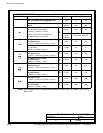
4+0
AC Output to Critical Load
F ull Load Current
(3) Phases, (1) N eutral, (1) Ground
G
Amps 668 288
NOTE: Callout letters D, F,andG map to drawing 164201535---4, sheets 3 of 5, 4 of 5,
and 5 of 5.