


29
Powerware
®
FERRUPS FE/QFE UPS (500 VA–18 kVA) Installation Guide : Rev A www.powerware.com
CHAPTER 5
EXTERNAL BYPASS SWITCH INSTALLATION
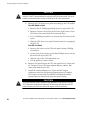
WARNING
Only qualified service personnel (such as a licensed electrician) should perform the
hardwired installation. Risk of electrical shock.
CAUTION
Before you install the bypass switch, verify that the bypass switch and the AC
disconnect switch are in the OFF position.
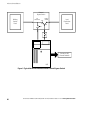
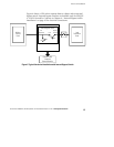
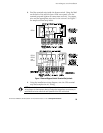
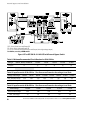
1. Identify the installation wiring diagram that applies to your
FERRUPS (see Table 9).
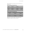
Table 9. External Bypass Switch Wiring Diagrams
Model (Frequency) UPS Input Voltage UPS Output Voltage Bypass Switch Type Wiring Diagram
FE 500 VA–3.1 kVA
(
6
0
H
)
120 120 MBB or BBM Figure 8 on page 36
(60Hz)
208 or 240
120/208 or 120/240 MBB or BBM
For 208V, use BBM only
Figure 9 on page 37
208 or 480 source*/
240 input
120/240 MBB or BBM Figure 10 on page 38
QFE 500 VA–3.1 kVA
(
5
0
H
)
120 120 MBB or BBM Figure 8 on page 36
(50 Hz)
220, 230, 240
220, 230, 240 MBB or BBM Figure 11 on page 39
FE 1.15 kVA–3.1 kVA
(60 Hz)
220 220 BBM Figure 8 on page 36
*With a step-up or step-down transformer.
**Contact your service representative for (a) single-phase installations that do not have the same input and output voltage,
or (b) split-phase installations that require 220 Vac.