


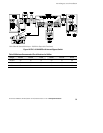
Internal Bypass Switch Installation
46
Powerware
®
FERRUPS FE/QFE UPS (500 VA–18 kVA) Installation Guide : Rev A www.powerware.com
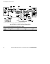
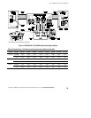
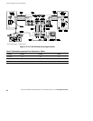
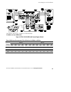
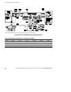
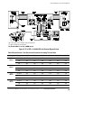
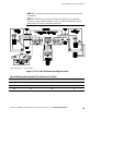
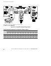
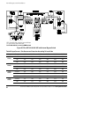
2. Review the installation wiring diagram and applicable notes to
find the proper circuit breaker size for your installation. In the
U.S., see Table 22 to size the wire. In other areas, use 75°C
copper wire and size according to the local code.
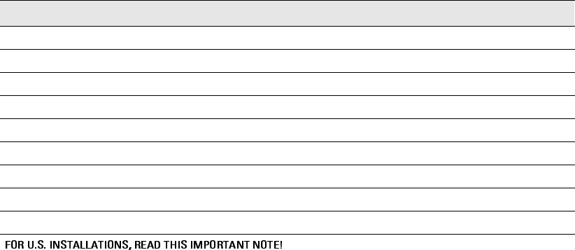
Table 22. Recommended Wire Sizes
Input Circuit Breaker Size 75°C Copper Wire Size
15A, 20A 12 AWG (3.3 mm
2
)
25A, 30A 10 AWG (5.3 mm
2
)
35A, 40A, 45A, 50A 8 AWG (8.4 mm
2
)
60A 6 AWG (13.3 mm
2
)
70A, 80A 4 AWG (21.2 mm
2
)
90A, 100A 3AWG(26.7mm
2
)
110A 2AWG(33.6mm
2
)
125A 1AWG(42.1mm
2
)
150A 1/0 AWG (53.5 mm
2
)
This table lists the AWG and mm
2
wire size for each circuit breaker size shown on the wiring diagrams. The minimum
recommended circuit breaker sizes for each model and voltage application are listed on the wiring diagrams.
Conductor sizes shall be no smaller than the 75°C wire size based on the ampacities given in Table 310–16 of the National
Electrical Code, ANSI/NFPA 70-1999, and article 220. All circuit conductors, including the neutral and equipment grounding
conductors, must be the same size (ampacity) wire. Code may require a larger AWG size than shown in this table because
of temperature, number of conductors in the conduit, or long service runs. Follow local code requirements.
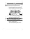
3. Remove the screws in the lower part of the bypass switch front
cover and remove the lower cover panel.
Remove the knockouts or plugs in the bottom of the bypass
switch for AC Line Input, AC from UPS Output, and AC to the
UPS load.
4. Install the conduit adapters. AC Input and AC Output
conductors must be run through separate pieces of conduit.
UPS output circuits shall be installed in dedicated conduit
systems and not shared with other electrical circuits.