


Battery Cabinet Installation
60
Powerware
®
FERRUPS FE/QFE UPS (500 VA–18 kVA) Installation Guide : Rev A www.powerware.com
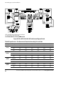
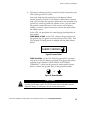
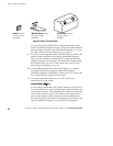
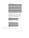
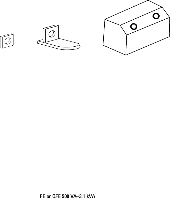
Square: Torque to
17 in lb or 1.9 Nm.
(BAT-0058)
Modified Square: Torque
to 35 in lb or 3.9 Nm.
(BAT-0065)
Screw Posts: Torque to
85 in lb or 9.6 Nm.
(BAT-0071)
Figure 23. Battery Terminal Types
Connect the battery cables between batteries as shown in the
battery installation diagram. Do not connect the cables between
battery strings or between the UPS and the batteries yet. If you
are only using one string of batteries, go to step 11.
9. If you are connecting more than one battery string, connect the
positive cables as shown in the battery installation diagram.
Next, use the voltmeter to check the DC voltage between the
negative terminals of the strings. The measured voltage should
be less than three volts. If it is more than three volts, correct
any wiring errors before you go on.
10. Use the cables provided to connect the negative (
–) battery
terminals of the battery strings as shown in the battery
installation diagram. If the battery cabinet has a DC switch, the
DC switch has been installed at the factory.
11. To connect external batteries to your UPS, follow the
instructions for your model:
If your battery cabinet has a DC switch, make sure the switch is
is in the OFF position; then, find the battery cables between the
UPS and the batteries. The removable DC connector at one end
of the cables connects to the UPS, and the other ends of the
positive and negative cables connect to the external batteries.
You should connect the cables to the batteries first. Refer to the
battery installation diagram as you follow the steps below.