


Battery Cabinet Installation
62
Powerware
®
FERRUPS FE/QFE UPS (500 VA–18 kVA) Installation Guide : Rev A www.powerware.com
NOTE If you have an external DC disconnect switch, see the instructions that came
with your disconnect switch.
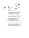
Now, turn the DC ON/OFF switch on the battery cabinet(s) to
the ON position. Leave the UPS DC switch in the OFF position.
12. Use the meter to check for proper nominal DC voltage at the
UPS end of the cable. Make sure the polarity agrees with the
markings on the UPS battery terminals.
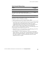
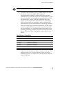
Table 29. Nominal Battery Voltage
Models Nominal Battery
Voltage
QFE 500 VA, 700 VA, 850 VA, 1.15 kVA, and 1.4 kVA 12 Vdc
FE 500 VA, 700 VA, and 850 VA 24 Vdc
QFE1.8kVA,2.1kVA,3.1kVA,4.3kVA,5.3kVA,and7kVA
FE 1.15 kVA, 1.4 kVA, 1.8 kVA, 2.1 kVA, 3.1 kVA, 4.3 kVA, 5.3 kVA,
and7kVA
48 Vdc
FE and QFE 10 kVA, 12.5 kVA, and 18 kVA 120 Vdc
After you have checked the DC voltage, turn the DC switch on
the battery cabinet(s) to the OFF position.
13. Complete the phase check beginning on page 8.