


Operation
30
Powerware
®
5115 Rack-Mount User’s Guide : 164201449 RevA www.powerware.com
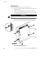
Standby Mode
When the UPS is turned off and remains plugged into a power outlet,
the UPS is in Standby mode. All indicators are off and power is not
available to your equipment. The battery recharges when necessary.
NOTE For 200–240V models, the output receptacles may remain electrically live (up
to 100–120V). Unplug the UPS to ensure power is not available to the output
receptacles.
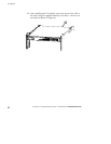
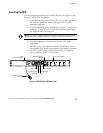
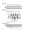
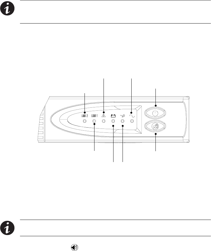
UPS Front Panel
The UPS front panel indicates the UPS status and also identifies
potential power problems. Figure 13 shows the UPS front panel
indicators and controls.
On/Off Button
Test/Alarm Reset Button
Power On Indicator (Green)
On Battery Indicator (Yellow) Overload Indicator (Red)
Service Indicator (Red)
Load Segment 2 Indicator (Green)
Load Segment 1 Indicator (Yellow)
Figure 13. UPS Front Panel
If the alarm beeps or a UPS alarm indicator stays on, see Table 8 on
page 48 to identify and correct the problem.
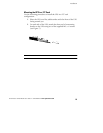
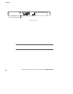
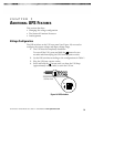
Initiating the Self-Test
NOTE Thebatteries must be fully charged and the UPS must not be in Battery mode
to perform the self-test.
Press and hold the button for three seconds to initiate the self-test. If
the UPS finds a problem, an LED indicates where the problem is. For
more information, see “Troubleshooting” on page 47.