


Additional UPS Features
32
Powerware
®
5115 Rack-Mount User’s Guide : 164201449 RevA www.powerware.com
Table 1. DIP Switch Settings
120V Models
Output Voltage Input Voltage Range DIPSwitch1 DIPSwitch2
110V 99V-116V ON OFF/ON
120V* 108V–127V* OFF OFF/ON
230V Models
Output Voltage Input Voltage Range DIPSwitch1 DIPSwitch2
220V 198V–233V ON OFF
230V* 207V–243V* OFF OFF/ON
240V 216V–254V ON ON
*Default position
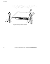
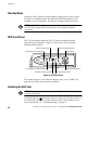
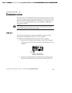
Network Transient Protector
The Network Transient Protector, shown in Figure 15, is located on the
rear panel and has jacks labeled IN and OUT. This feature
accommodates a single RJ-45 (10BaseT) network connector.
Low voltage models can also accommodate an RJ-11 telephone
connector that provides protection for modems, fax machines, or other
telecommunications equipment. As with most modem equipment, it is
not advisable to use this jack in digital PBX (Private Branch Exchange)
environments.
NOTE DONOT connect any telephone or fax/modem equipment to the 230V models;
only network protection is available for 230V models.
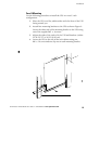
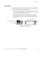
1. Connect the input connector of the equipment you are
protecting to the jack labeled IN.
2. Connect the network or telephone cable (low voltage models
only) to the jack labeled OUT.
OutIn
Figure 15. Network Transient Protector