


TIE CABINET INSTALLATION
EATON Powerware
®
9355 Tie Cabinet (20/30 kVA)Installation Guide S 164201630 Rev A www.powerware.com
15
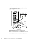
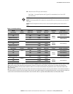
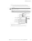
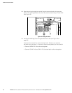
22. Wire the maintenance bypass auxiliary contacts and terminate to the
maintenance bypass wires in the Tie Cabinet (see Figure 6 on page 12).
Connect the black and the red wire to TB4 on the UPS (see Figure 9). Cap the
blue wire.
NOTE The maintenance bypass contacts are normally-open. To ensure proper bypass operation, DO NOT
use the blue wire (it is normally-closed).
NOTE There are two sets of maintenance bypass wires; you can terminate to e ither set. If you are
installing four UPSs, it is recommended to terminate two UPSs to one set of wires and two UPSs to the other
setofwires.
From UPS 4 Output
From UPS 3 Output
From UPS 2 Output
Red Wires
(open when breaker is open)
Bypass Input
Black Wires
(common)
From UPS 1 Output
350A
110A (4X)
LOAD
Blue Wires
(closed when breaker is open)
350A Breaker
Auxiliary Contacts
Figure 9. Parallel Wiring Diagram
23. Reinstall the UPS wiring access cover.
24. Reinstall the UPS conduit landing box in the reversed position.