


INSTALLING OPTIONS
EATON Powerware
®
9355 Tie Cabinet (20/30 kVA)Installation Guide S 164201630 Rev A www.powerware.com
21
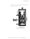
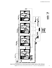
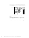
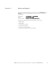
4. Set the jumper pins on the Powerware Hot Sync CAN Bridge Card according to
the parallel configuration (see Figure 15):
S If only two UPSs are paralleled, then set both cards to Pins 1 and 2.
S For three or four paralleled UPSs, set the cards of the first and last UPSs to
Pins 1 and 2; set the cards for the middle UPSs to Pins 2 and 3.
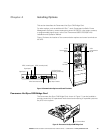
Jumper J7 - Pins 1 and 2
Jumper J7 - Pins 2 and 3
Figure 15. Setting the CAN Bridge Card Jumper J7 (Side View)
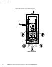
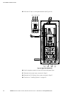
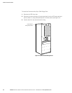
5. Install the CAN Bridge Card into X-Slot 2 (see Figure 12 and Figure 17).
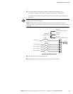
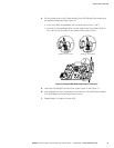
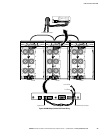
6. Strip shielded, four-wire, twisted-pair wire (maximum 18 AWG recommended)
for CAN Bridge Card wiring and pull-chain wiring.
7. Repeat Steps 1 through 6 for each UPS.