


EATON Powerware
®
9355 Tie Cabinet (20/30 kVA)Installation Guide S 164201630 Rev A www.powerware.com
19
Chapter 4 Installing Options
This section describes the Powerware Hot Sync CAN Bridge Card.
For other options, such as additional X-Slot
t cards, Powerware LanSafe
®
Power
Management Software, remote emergency power-off (REPO), relay output contacts,
or programmable signal inputs, refer to the Powerware 9355 UPS (20/30 kVA)
Installation and Operation Manual.
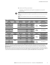
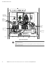
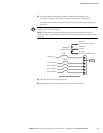
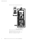
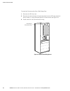
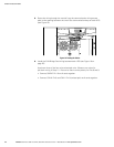
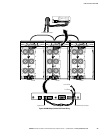
Figure 12 shows the location of the communication options and control terminals on
the UPS.
DB-9 Communication Port
REPO (normally open)
Signal Input2
Signal Input1
X-Slot
Communication
Bay #2
X-Slot
Communication
Bay #1
Relay Output Contacts
Control
Terminals
REPO (normally closed)
Pull-Chain Output
Contacts (parallel only)
Figure 12. Communication Options and Control Terminals
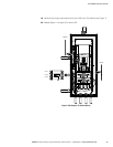
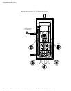
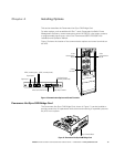
Powerware Hot Sync CAN Bridge Card
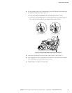
The Powerware Hot Sync CAN Bridge Card, shown in Figure 13, can be installed to
provide connectivity for operational mode control and metering of a parallel system at
any UPS in the system.
Plug-in Terminal Block
Figure 13. Powerware Hot Sync CAN Bridge Card