


INSTALLING OPTIONS
EATON Powerware
®
9355 Tie Cabinet (20/30 kVA)Installation Guide S 164201630 Rev A www.powerware.com
22
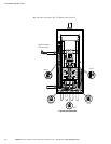
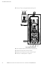
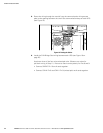
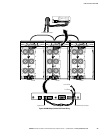
8. Route the wiring through the conduit from the communication wiring access
plate to the opening between the two X-Slot communication bays on each UPS
(see Figure 16).
Figure 16. Routing the Cables
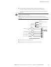
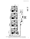
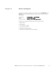
9. Install the CAN Bridge Card wiring between each UPS (see Figure 18 on
page 25).
Use three wires of the four-wire twisted-pair wire. (Reserve two wires for
pull-chain wiring in Step 11.) Be sure to check correct polarity for Pins 8 and 9:
S Connect SHIELD Pin 10 on all cards together.
S Connect CAN H Pin 9 and CAN L Pin 8 (twisted pair) on all cards together.