


INSTALLING OPTIONS
EATON Powerware
®
9355 Tie Cabinet (20/30 kVA)Installation Guide S 164201630 Rev A www.powerware.com
24
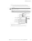
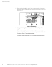
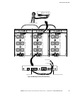
11. Wire the pull-chain wiring to Signal Input 2 on each UPS and daisy chain the
wiring to each UPS as shown in Figure 18. Be sure to check correct polarity:
S Connect Pull-Chain Output Contact Pin 1 to Signal Input 2 Pin 1 on each UPS.
S Connect Pull-Chain Output Contact Pin 2 to Signal Input 2 Pin 2 on each UPS.
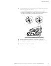
CAUTION
If polarity or wiring is not correct, the parallel system does not operate normally. For example, when shutting
down one UPS, the remaining UPS transfers the load to bypass instead of supporting the load. Verify all CAN
Bridge Card wiring is correct for proper operation.
NOTE Signal Input 2 can still be used for building alarms; it is automatically rerouted to the CAN Bridge
Card.
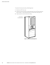
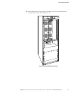
12. Reinstall the communication wiring access plate on each UPS.
13. Replace the UPS front door on each UPS.