


4–Hardware Installation
QLE3142 Installation
NE0154601-00 C 4-5
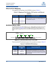
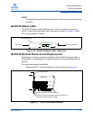
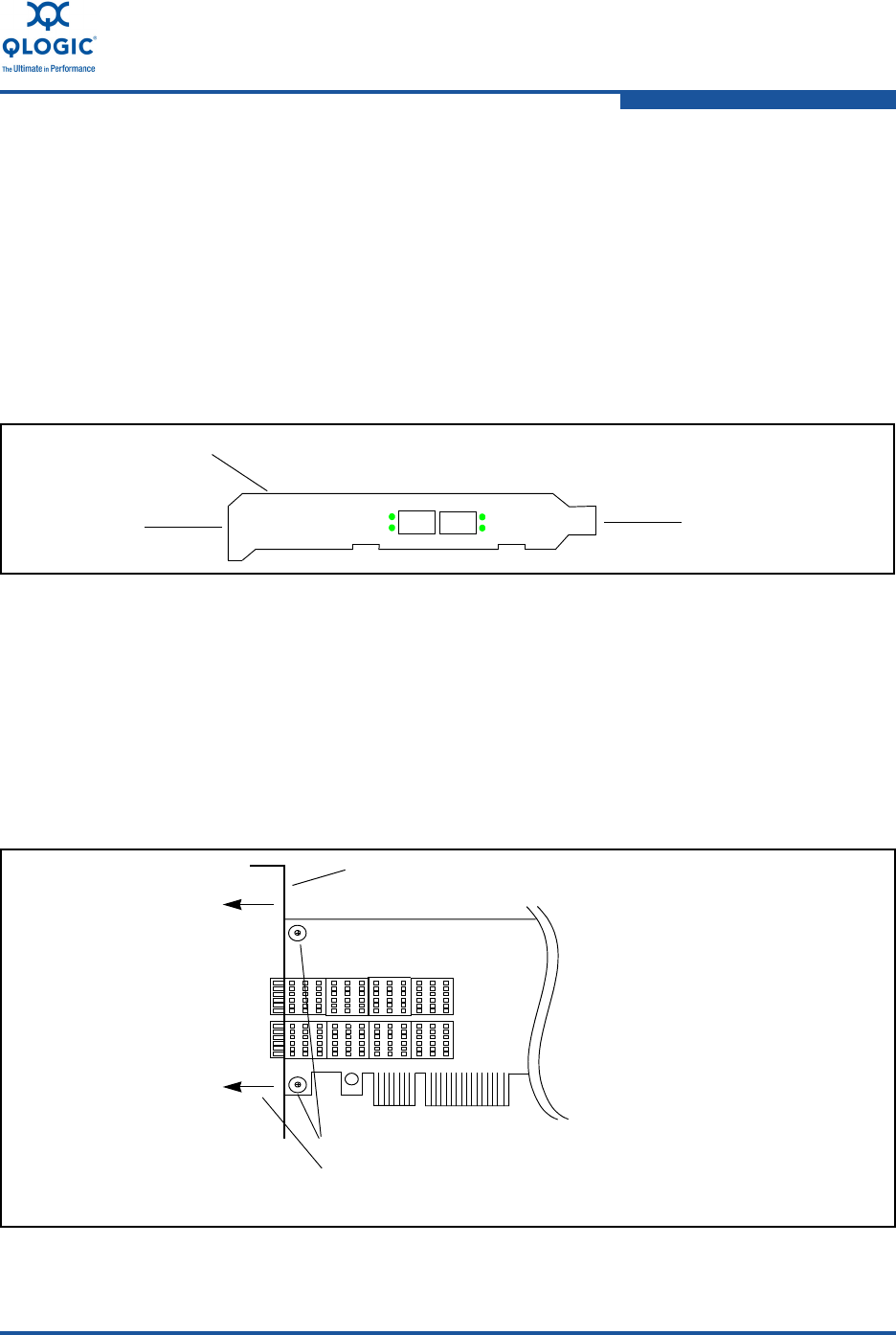
QLE3142 Status LEDs
The QLE3142 has two status LEDs per port, one for link status and one for
activity. These LEDs are located next to the ports as shown in Figure 4-6. Both
SFP+ ports operate at 10Gbps.
Figure 4-6. QLE3142 Status LEDs—Side View
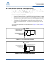
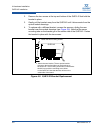
QLE3142 Bracket Removal and Replacement
Depending on the type of system, installation of the QLE3142 requires either a
long bracket or a short bracket. QLogic provides both of these brackets with the
product.
To remove and replace the bracket:
1. Remove the SFP+ optical modules from their housing (see Figure 4-7).
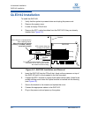
Figure 4-7. QLE3142 Bracket Removal
NOTE:
The optical module must be seated correctly in the housing to ensure proper
operation.
Port 1Port 2
Link
Link
Activity
Activity
Mounting bracket
Top of card
PCIe connector end
QLE3142
Housing
Housing
Mounting Bracket
1.Remove the two mounting screws.
2.Gently pull the bracket away from the board until it
clears the optical module housings.