


Power Distribution 2 – Hardware Installation
2-6 FC0151103-00 E
2.3
Power Distribution
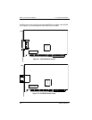
The QLA2200/2200L board supplies +5 volts to pin 7 of the HSSDC copper interface
to support an external media interface adapter (MIA), if required. (An MIA converts
copper bus signals to optical bus signals.)
2.4
Installation in the Computer
Perform the following steps to install the QLA22xx board in your PC:
1. Check the motherboard and make any configuration changes necessary to
accommodate the QLA22xx board.
The QLA22xx board is self-configuring; however, some motherboards
require manual configuration. For example, some systems have a PCI
Device Configuration menu in the motherboard setup BIOS where you must
enable host adapter boards, bus master slots, and interrupt request (IRQ)
levels. If the motherboard supports triggering, use level triggering for the
QLA22xx board. See the documentation supplied with your computer, or
contact your computer dealer to determine if your motherboard requires
configuration.
2. Power down the peripherals, then the computer.
3. Remove the computer cover and save the screws.
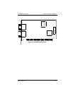
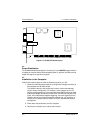
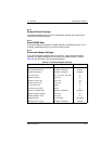
J2
SERIAL NUMBER
J1
ISP CHIP
ISP CHIP
Figure 2-7. QLA2212F Board Layout
J3
J4
TX RX