


21
Controller Board
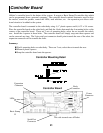
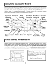
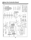
ARobot’s controller board is the brains of the system. It accepts a Basic Stamp II controller chip which
can be programmed from a personal computer. The controller board contains electronics used to drive
the motors, sound the speaker, control the LEDs, read whiskers, etc. An expansion port allows addi-
tional circuits to be added to the system.
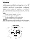
The controller board is mounted to the robot body using 4) 1” plastic spacers and 4) 6-32 x 1/4 screws.
Place the controller board on the robot body and find the 4 holes that match the 4 mounting holes on the
corners of the controller board. There are 2 sets of mounting holes, select the set towards the robot's
rear. Install the 4 spacers in those holes. The controller board will simply snap onto these spacers and
can be removed any time. The 9 pin serial port connector should point towards the rear of the robot, the
expansion connector will be towards the front.
Summary:
Find 4 mounting holes on robot body. There are 2 sets, select the set towards the rear.
Mount 4 plastic spacers.
Snap the controller board onto the spacers.
Controller Board
Controller Mounting Detail
Expansion
Connector
Serial Port
Connector
Basic Stamp
II
LEDs
Body
Connector
Power
Connector
This side towards rear of Robot