


Coprocessor Command Summary
33
This section describes how the coprocessor works and how each command is constructed.
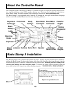
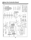
The controller board contains a coprocessor that is used to control the drive motor, powerful output, en-
coder sensor, and the 4 RC servo motors (#1 is used as the steering motor). This frees the Basic Stamp
II for other tasks. The coprocessor receives commands from the Basic Stamp II via the coprocessor net-
work bus on pin P8. SERIN and SEROUT commands are used in PBasic to communicate with the co-
processor. Each command sent to the coprocessor is preceded by a “!“ start character and an address
character. This allows other coprocessors to be attached to the network.
The coprocessor responds to some commands by returning an “A” to indicate “acknowledged”. The co-
processor never speaks until spoken to – this is called a “Master/Slave“ network. The Basic Stamp II is
the master and the coprocessor is the slave. This creates a multi-processor system.
Each command intended for the motor control coprocessor begins with “!1”
Drive Motor Control:
Example: !1M11200E7
The command begins with “!1M1” to indicate the drive motor. The next character (1 in the example)
indicates the direction 1=forward, 0=reverse. The next character (2 in the example) is the speed which
should be 0, 1, 2 ,3 ,4 ,5 ,6 ,7 ,8 ,9 ,A. Speed of 0 is off, A is full speed. The next 4 characters are the
desired encoder count in hexadecimal (00E7 in the example). Each encoder count represents about 1/2”
of travel. When this command is given the current encoder count is reset. If the command is accepted,
an “A” will be returned indicating “acknowledged“.
Read The Encoder Count:
Example: !1E1
This command asks the coprocessor to return the current encoder count as 4 hexadecimal digits which
represents the current distance that the robot has traveled. Each encoder count represents about 1/2” of
travel.
Continued on next page…….