


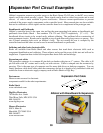
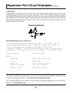

Analog Inputs -
Analog inputs are inputs that can vary from 0 to 5 volts. While the Basic Stamp II doesn’t have a true
analog input, analog signals can be read using a little trick. This is done by adding a capacitor to ground
on a digital I/O pin and a resistive sensor to +5 volts. The sensor value can be read by first setting the
digital I/O pin low to drain the capacitor, then the I/O pin is changed into an input, the resistive sensor
will gradually charge the capacitor towards +5 volts. The time it takes for the signal to read a logic one
(high) is the value of the sensor.
Expansion Port Circuit Examples
continued
41
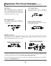
Basic Stamp II light sensor example code
'This routine demonstrates detecting light. The light level is
'read by determining the time it takes to charge the capacitor.
'The CDS photodetector changes resistance as the light
'intensity changes. This changes the current that is charging the
'capacitor. The output result is then output to the debug screen.
light var word 'light variable.
main:
pause 500 'check every half a sec.
low 2 'drain cap.
pause 50 'wait for cap to drain.
rctime 2,0,light 'time cap charging.
debug ? light 'send result to PC.
More expansion information
Our space is limited here so make sure to visit our web site for the latest expansion application notes
complete with program examples. www.robotics.com/arobot/projects.html
Also visit the Parallax web site which has an entire section dedicated to application notes for the Basic
Stamp II. www.parallaxinc.com
Analog Light Sensor