


Whiskers
30
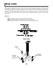
Whisker wires are used to detect objects while the robot is moving. There is a left and right whisker
which can be read separately to determine the location of the object. The left whisker is connected to
the P0 pin and the right whisker is connected to the P1 pin. When an object is detected, these pins return
a logic zero (low). The pins must be in the input mode. The following PBasic code example shows
how the whiskers can be read.
if in0=0 then wh1 'If left whisker on then jump to wh1.
if in1=0 then wh2 'If right whisker on then jump to wh2.
See the WANDER and TEST program for examples on how to use the whiskers for navigation.
It is possible to attach additional whiskers to the robot. Simply wire them to unused Basic Stamp pins
available on the expansion connector and read them in your program. Mounting holes are provided for
side and rear whiskers.
Speaker
A speaker is connected to P9 on the Basic Stamp II. It can be used to send various signals to the opera-
tor. Simply toggle the pin at various frequencies to create different tones. Here’s a PBasic code exam-
ple:
speaker con 9 'Define speaker pin to 9.
freqout speaker,200,1500 '200=frequency, 1500=duration.
low speaker 'Finish with pin LOW.
It’s very important to leave the speaker output pin LOW when done or power will be drained from the
battery. This pin should also be set LOW upon program startup. See WANDER and TEST programs
for additional examples.
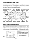
LED indicators
Green and red LED (Light Emitting Diodes) are mounted on the controller board and are connected to
the Basic Stamp II pins P10 (red) and P11 (green). A low condition will turn an led on. Here’s a PBasic
code example to control them:
redled con 10 'Define red led pin.
grnled con 11 'Define green led pin.
low grnled 'Green LED on.
high redled 'Red LED off.
To help conserve battery power, turn off the LEDs when not needed.