


151
E-DOC-CTC-20051017-0151 v1.0
Chapter 5
Expert Configuration
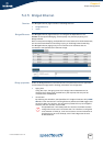
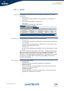
5.4.7 Routed IPoA
Creating a new Routed
IPoA Ethernet Interface
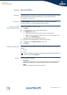
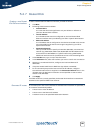
To add a new Routed IPoA Ethernet interface, proceed as follows:
1 Click New.
2 Following fields become available:
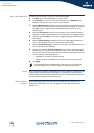
Interface Name:
Is a name that has local significance only and allows to reference a
particular Routed IPoA interface
Local IP Address:
Is an IP address that must be configured on the local Routed IPoA
Ethernet interface and is provided by your ISP or system administrator.
Remote IP address:
Is an IP address that is configured on the device connected at the remote
end of the ATM virtual channel and is again supplied by your ISP or
system administrator
Destination Network:
This input field allows to specify all networks (0.0.0.0/0), a summarized
network (e.g. 20.0.0.0/24, 20.0.1.0/24, 20.0.2.0/24 and 20.0.3.0/24 can be
summarized into 20.0.0.0/22) or a specific network (e.g. 20.0.0.0/24).
Additional networks can be specified via entries in the forwarding table.
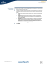
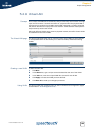
3 In the Interface box, type a unique interface name.
4 In the Destination list, select the interface you want to use for this connection.
5 Assuming a numbered IPoA link, configure the Local and Remote IP
addresses.
6 If required enable NAPT via the NAPT box (by default unchecked)
7 For IP connectivity beyond the local and remote IP address, a single or
summarized network can be supplied in the Destination Network field. In the
ultimate case "all destination networks" can be specified via the so-called
default route (0.0.0.0/0).
8 Click Apply.
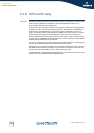
If all field values are correctly specified, the Routed IPoA interface is created and
attached to the specified ATM virtual channel.
Generated IP routes In the assumption that Local IP, Remote IP and Destination Network are specified, 3
IP routes are automatically added:
A host route to Local IP address
A host route to the Remote IP address
A network route to the specified Destination Network.