


M301N2T-PRB User’s Manual 1. Outline
REJ10J0037-0100 Rev.1.00 Mar.16, 2005
Page 16 of 48
1.4 Specifications
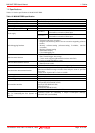
Tables 1.5 lists the specifications of the M301N2T-PRB.
Table 1.5 M301N2T-PRB specification
Item Desctiption
Applicable MCU M16C/1N Group
Evaluation MCU M301N2RGP (1 piece)
Usable MCU mode Single-chip mode
Applicable power supply 4.2--5.5V
Operating frequency 4.2--5.5V 16MHz, 0 wait
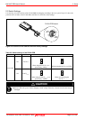
XIN-XOUT
Internal oscillator circuit board (OSC-3)
Switchable to external oscillator input
Clock supply
X
CIN-XCOUT
Internal oscillator circuit (fixed 32.768kHz)
Switchable to external oscillator input
Basic debugging functions
- Download
- Software break (max. 64 points)
- Program execution/stop (allows free-run execution supporting software
breaks)
- Memory reference/setting (reference/setting C-variables, run-time
execution)
- Register reference/setting
- Disassemble display
- C-level debugging, etc.
Real-time trace function
- 32K-cycle bus information recordable
(Bus, external trigger, time stamp)
- 5 trace modes supported (Break/Before/About/After/Full)
- Can be recorded ON/OFF by events
Real-time RAM monitor function
- 1,024 bytes
- Data/last access result
Hardware break function 6 points (Bus detection, interrupt, external trigger signal)
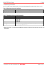
Execution time measurement function
Time between program start and stop
Maximum/minimum/average execution time and pass count of specified
four zones.
Count clock: Equal to MCU Clock or 16 MHz
C0 coverage 256KB
Event output Break x1, Event x6
External trigger input TTL level x8
Host machine interface
Dedicated parallel (PC4701HS)
LPT parallel (PC4701M/PC4701U)
Serial (PC4701HS/PC4701M)
USB (PC4701U)
LAN (PC4701HS/PC4701U)
Power supply to emulator AC100V--120V, AC200--240V (50/60Hz)
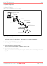
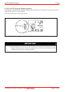
Connection to user system
(see "2.5 Connecting the User System" on
page 23)
Converter board for connecting a 48-pin 0.5-mm-pitch (48P6Q):
M30102T-PTC (not included)