


M301N2T-PRB User’s Manual 2. Setup
REJ10J0037-0100 Rev.1.00 Mar.16, 2005
Page 18 of 48
2. Setup
This chapter describes the preparation for using this product, the procedure for starting up the emulator and how to change
settings.
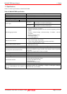
2.1 Selecting Clock Supply
2.1.1 Clock Supply to the MCU
There are two ways to supply a clock to the MCU, using the oscillator circuit of the emulation pod or using the oscillator
circuit on the user system. Table 2.1 lists the factory-settings of each clock supply when you install the emulator debugger.
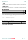
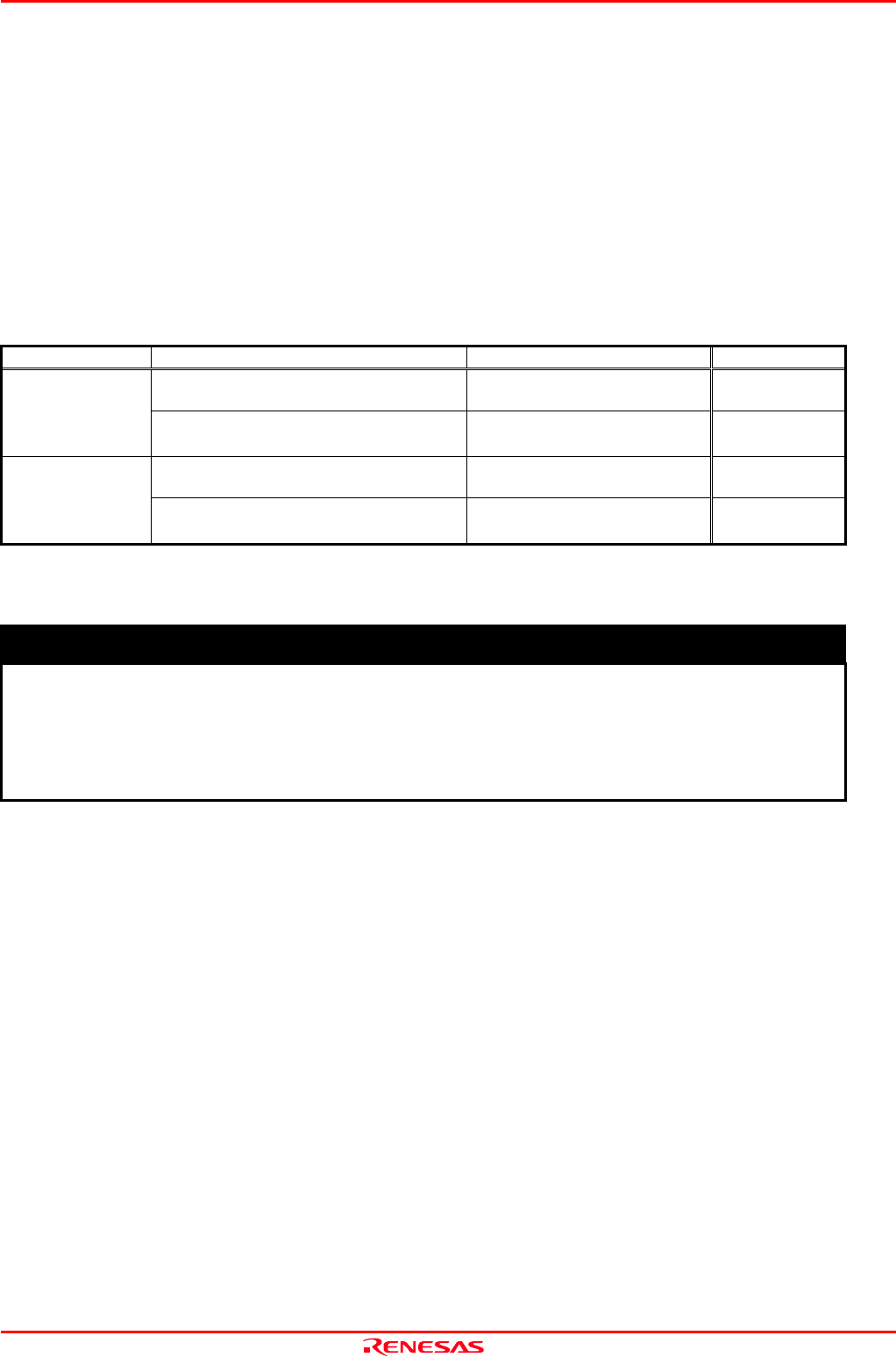
Table 2.1 Clock Supply to the MCU
Clock Description Display of emulator debugger Default setting
Internal oscillator circuit of emulation pod
(OSC-3: 16.0 MHz or OSC-2)
Internal Yes
XIN-XOUT
User system External -
Internal oscillator circuit of emulation pod
(32.768 kHz)
Internal -
XCIN-XCOUT
User system External Yes
IMPORTANT
Note on Changing the Clock Supply:
The clock supply can be set in the Init dialog box when starting up the emulator debugger or inputting
CLK command on the script window.
For pins X
CIN
-X
COUT
, it is necessary to set the switches in the M30100T3-RPD-E. For details, refer to
"2.2 Switch Settings" (page 20)
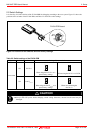
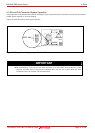
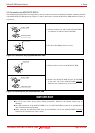
2.1.2 Using the Internal Oscillator Circuit Board
An oscillator circuit board for 16.0 MHz (OSC-3) is pre-mounted on the emulation pod M30100T3-RPD-E. Also the oscillator
circuit board (OSC-2) is attached to change the oscillation frequency. When you use an internal oscillator circuit as a main
clock, “Internal” can be set by the emulator debugger. For details on replacing the oscillator circuit board, refer to the
M30100T3-RPD-E user’s manual.
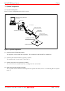
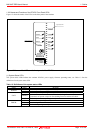
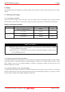
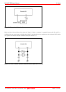
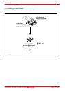
2.1.3 Using the Oscillator Circuit on the User System
To operate this product with an external clock, construct the oscillator circuit as shown in Figure 2.6 in the user system and
input the oscillator output at 50% duty (within the operating range of the evaluation MCU) into pin X
IN
. And pin X
OUT
should
be open. Choose "External" in the emulator debugger to use this clock.