


M301N2T-PRB User’s Manual 2. Setup
REJ10J0037-0100 Rev.1.00 Mar.16, 2005
Page 19 of 48
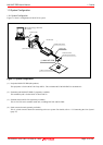
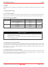
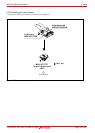
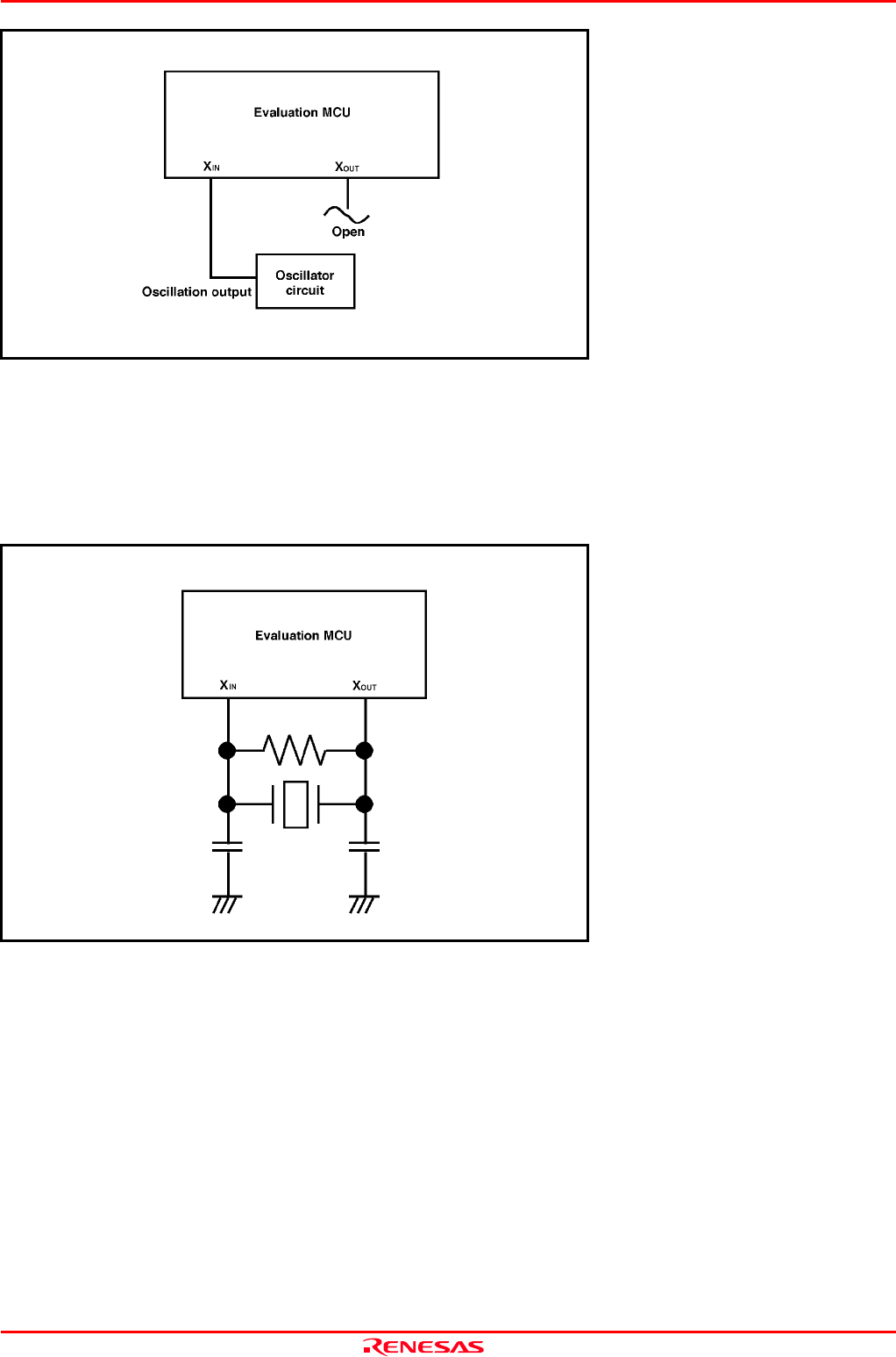
Figure 2.1 External oscillator circuit
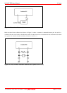
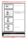
Make note that in the oscillator circuit shown in Figure 2.2 where a resonator is connected between pins X
IN
and X
OUT
,
oscillation does not occur because a flexible cable, buffer IC and other devices are used between the evaluation MCU and the
user system. It is same for sub-clock oscillator circuits (X
CIN
and X
COUT
).
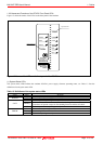
Figure 2.2 Circuit in which oscillation does not occur (same for X
CIN
-X
COUT
)