


M301N2T-PRB User’s Manual 4. Hardware Specifications
REJ10J0037-0100 Rev.1.00 Mar.16, 2005
Page 38 of 48
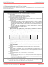
IMPORTANT
Notes on Address-Match Interrupts:
To debug address-match interrupts, set a software break or hardware break at the top address of the
address-match interrupt process. If you set a software break or hardware break at an address where an
address-match interrupt occurs, the program may run out of control.
When an address at which an address-match interrupt occurs is executed in one-step mode, the program
stops after executing the first instruction after returning from the address-match interrupt processing.
Note on BRK Instruction and BRK Interrupt:
With this emulator system, a BRK interrupt by a BRK instruction is exclusively used for software
break functions. Therefore, you can not use them for your program.
Notes on Software and Hardware Breaks:
The software break generates BRK interrupts by substituting the proper instruction to the BRK
instruction "00h". Therefore, when referencing the result of a trace in bus mode, "00h" is displayed for
the instruction fetch address where a software break is set, and when referencing in disassemble mode,
"BRK" instruction is displayed.
It is not possible to use a software break and a hardware break at the same time. If doing so, it may not
operate normally.
In the area where the MAP setting is EXTERNAL, software breaks cannot be used.
Note on Stop and Wait Modes:
Do not single step an instruction shifting to stop or wait mode. It may cause communication errors.
Note on Watchdog Function:
The MCU's watchdog timer can be used only while programs are being executed. To use it otherwise,
disable the watchdog timer.
Note on Protect Register (PRC2):
Make note of the fact that the protect is not canceled when protect register (PRC2), which enables
writing in the port P0 direction register, is changed with the below procedure.
(1) Step execution of the "instruction for setting ("1") PRC2"
(2) Execution from the instruction setting "1" to PRC2 where a software breakpoint is set
(3) Setting the break point from the "instruction for setting ("1") PRC2" to when the "setting the port
P9 direction register and the SI/Oi control register"
(4) Setting ("1") PRC2 from the dump window or script window
Note on Accessing Addresses 00000h and 00001h:
With the M16C/10 Series MCUs, when a maskable interrupt is generated, the interrupt data (interrupt
number and interrupt request level) stored in addresses 00000h and 00001h are read out. Also, the
interrupt request bit is cleared when address 00000h or 00001h is read out. Consequently, when the
address 00000h readout instruction is executed or when address 00000h or 00001h is read out in the
cause of a program runaway, a malfunction occurs in that the interrupt is not executed despite the
interrupt request, because the request bit of the highest priority interrupt factor enabled is cleared.
For this malfunction, when the reading out to the address 00000h or 00001h is generated excluding the
interrupt, the WANING LED (yellow) lights up to alarm. When this LED lights, there is a possibility
of wrong access, therefore check the program. This LED is turned off by the system reset switch of the
emulator main unit.