


( 16 / 40 )
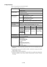
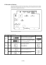
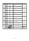
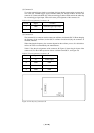
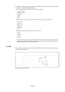
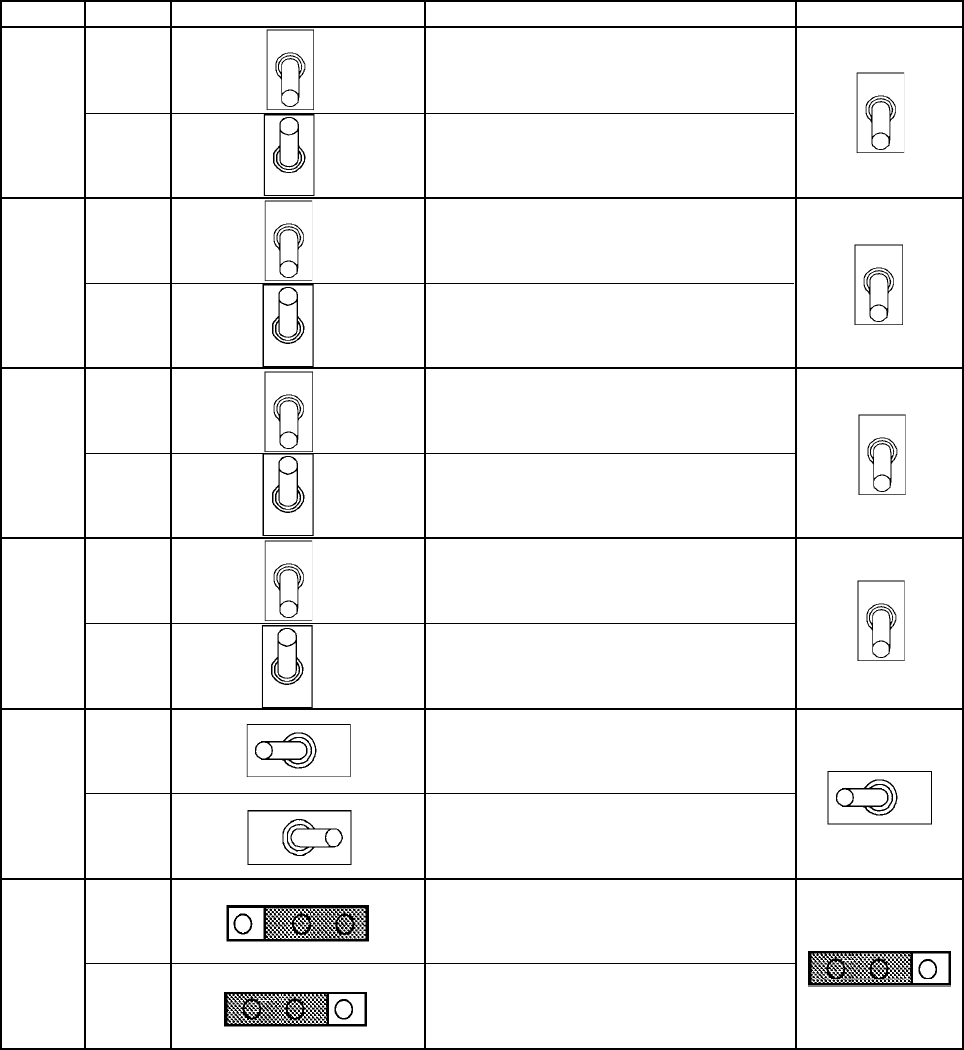
Table 4.3 Functions of the switches (2/2)
Factory-setting
DescriptionSwitch positionLabel
Does not connect the pullup resistor 68 kΩ to
the port P10.
Connects the pullup resistor 68 kΩ to the port
P1
0.
Does not connect the pullup resistor 68 kΩ to
the port P11.
Connects the pullup resistor 68 kΩ to the port
P1
1.
Does not connect the pullup resistor 68 kΩ to
the port P1
2.
Connects the pullup resistor 68 kΩ to the port
P1
2.
Does not connect the pullup resistor 68 kΩ to
the port P1
3.
Connects the pullup resistor 68 kΩ to the port
P13.
Uses the ports D
6 and D7.
Uses the sub-clock oscillator circuit.
SW4
SW5
SW6
SW7
SW8
SW9
OFF
ON
OFF
ON
OFF
ON
OFF
ON
551
555
PORT
XC
OFF
OFF
OFF
OFF
PORT
555
Operates the M34551T2-MCU for 4551 group.
Operates the M34551T2-MCU for 4555 group.
PORT XC
PORT XC
555
551
555
551