


( 27 / 40 )
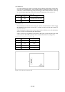
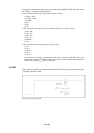
5.4 Switch Settings
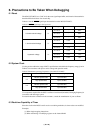
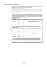
The PCA7745 board is equipped with switch SW1 for setting the ROM type. Set switch SW1
according to the type of EPROM to be used as shown in Table 5.1.
Table 5.1 Setting switch SW1 on PCA7745
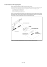
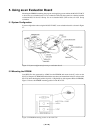
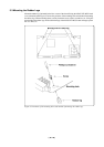
5.5 Connection to the Target System
For method of connecting the MCU board to the target system when using this product as an
evaluation board, refer to "4.5 Connecting the MCU board to the Target System".
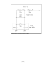
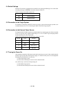
5.6 Connection to the External Power Source
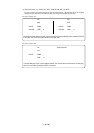
If using the M34551T2-MCU board as an evaluation board, you must supply power from an external
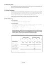
source. Use a power source capable of delivering +5 V or +12 V. Table 5.2 gives the pin positions
for the external power source input cable.
Table 5.2 Pin positions for the external power source input cable
5.7 Turning the Power On
After checking connection of the target system and external power source for the evaluation board,
turn the target system and external power supply on. And turn on the power to each equipment
following the procedure below successively.
(1) Turn on the target system.
(2) Turn on the external power source for the evaluation board.
Also, follow steps (1) and (2) when powering off.
(1) Turn off the target system.
(2) Turn off the external power source for the evaluation board.
Setting
256
512
Device
M5M27C2566AK
M5M27C512ALK
Pin No.
1
2
3
4
Color
Red
Black
White
-
Function
Input (+5 V)
GND
Input (+12 V)
Not used