


( 23 / 40 )
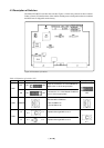
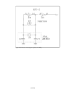
Some signals connected to the target system are emulated on the M34551T2-MCU board. For details,
see "Chapter 7. Connection Circuit Diagram".
• Pins connected directly to the target system (6 types, 24 lines)
(1) SEG0 - SEG15
(2) COM0 - COM3
(3) CARR
(4) D6*
(5) D7*
(6) VSS
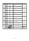
• Pins connected to the target system via emulation circuits, etc. (6 types, 20 lines)
(1) P00 - P03
(2) P10 - P13
(3) P20 - P23
(4) D0 - D5
(5) RESET *
(6) VDD
• Pins not connected to the target system (5 types, 5 lines)
(1) XIN
(2) XOUT
(3) CNVSS
(4) XCIN *
(5) XCOUT *
* Not connected to the target system when the sub-clock is selected (switch SW8: "XC"). The
external clock signal (32.768 kHz) is input to the X
CIN
pin from the oscillator of the M34551T2-
MCU board. And the X
COUT
pin is not connected.
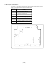
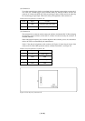
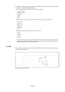
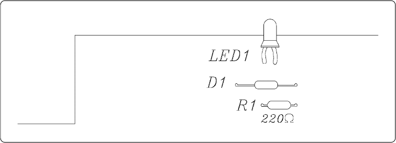
4.6 LED
Figure 4.9 shows the LED layout of the M34551T2-MCU. The LED lights in green when the power
is supplied to the MCU board.
Figure 4.9 Layout of the LED