


( 35 / 40 )
6.10 External Trigger
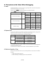
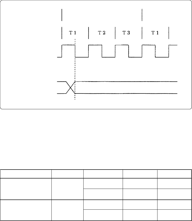
(1) External trigger input timing
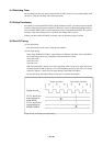
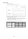
The latch timing of the external trigger is shown in Figure 6.2.
(2) External trigger signal input characteristics
Trigger breaks work according to the condition (leading edge/trailing edge) of signals input from
the external trace cable. The external trigger signals of the trace points and the external trigger
signals of the break points use the same signals.
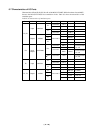
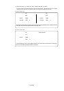
The input characteristics of the external trigger are shown in the Table 6.4 below.
Figure 6.2 Latch timing of the external trigger signal
External trigger signal
TRIG
System clock
X
IN
Instruction
Next instruction
Table 6.4 External trigger input characteristics
H-level input Voltage
L-level input voltage
Item Voltage
V
cc = 2.0 V
Vcc = 4.5 V
Vcc = 2.0 V
Vcc = 4.5 V
Symbol
V
IH
VIL
Max.
-
-
0.5 V
1.35 V
Min.
1.5 V
3.15 V
-
-