


( 19 / 40 )
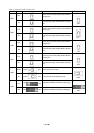
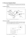
(2) Connector J4
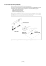
To use the external trigger signal as event input of trigger breaks or trace points, connect the 2-
wire cable (for external trigger signal) included with your M34551T2-MCU board to the
connector J4. Connect the black clip of the external trigger cable to GND, and use the white clip
for external trigger signal input. Table 4.6 lists the pin assignments of the connector J4.
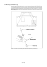
Table 4.6 Pin assignments of connector J4
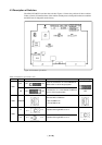
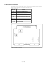
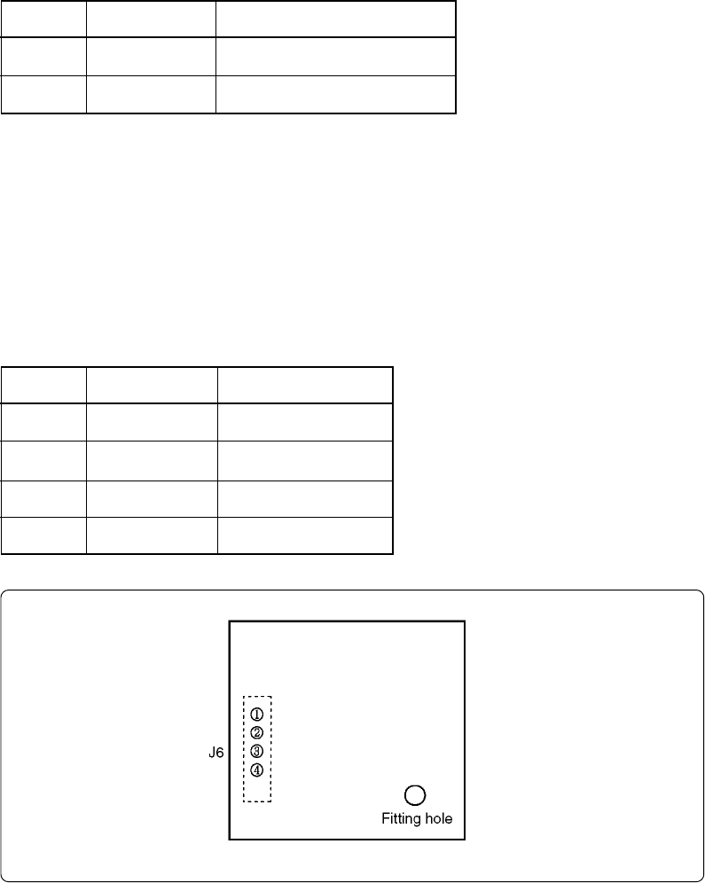
Figure 4.5 Pin layout of connector J6
(3) Connector J6
The connector J6 is a connector used to connect an oscillator circuit board OSC-2. When changing
the frequency of the oscillator, use the OSC-2 oscillator circuit board (only the connector J1
mounted) included.
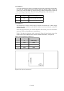
When changing the frequency, the constants depend on the oscillator you use. It's advisable to
refer to the values recommended by the manufacturers.
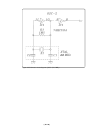
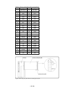
Table 4.7 lists the pin assignments of the connector J6. Figure 4.5 shows the pin layout of the
connector J6. For the 4 MHz operation with an oscillator board OSC-2, see Figure 4.6.
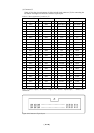
Table 4.7 Pin assignments of connector J6
Pin No.
1
2
Signal
TRIG
GND
Function
External trigger signal input
GND input
Pin No.
1
2
3
4
Signal
VCC
GND
CLK
GND
Function
Power supply
GND
Clock input
GND